This thread has been locked.

If you have a related question, please click the "Ask a related question" button in the top right corner. The newly created question will be automatically linked to this question.

UCD74120: Generating CVDD of 1.1V for higher currents

Part Number: UCD74120
Other Parts Discussed in Thread: TCI6636K2H, , TMS320C6678, UCD9244-EP, UCD9244

Hi,

I am using TMS320C6678 processor. The variable core voltage CVDD is consuming around 15A. Since UCD7242 has a 10A limitation, we have used UCD74120 as shown in the EVM of K2H-K2E (K2H_K2EVM-HK_SCH_A104_Rev4_0.pdf)

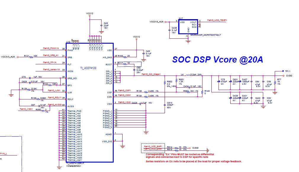
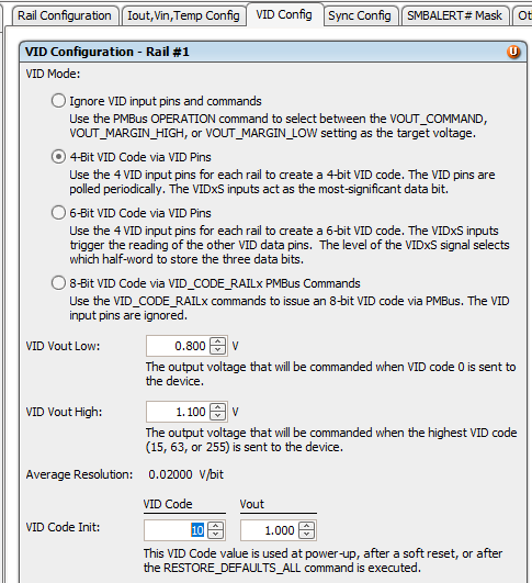
We have selected this circuit diagram after discussing this forum. However, we have found that the device TCI6636k2H has initial CVDD of 1V while TMS320C6678 has an initial voltage of 1.1V. What circuit parameter can we change in the above diagram to get 1.1V?


Best Regards,

Binayak

  • Hi Binayak,

    Can you provide the whole schematic including the controller, TCI6636k2H and TMS320C6678? The output voltage is controlled by the controller, not UCD74120. So I would like to see how the voltage is feedback to the controller and how it was connected to TCI6636k2H and TPMS320C6678. Thanks.

    Regards,

    Weidong

  • Hi Weidong,

    I am sharing the schematic portions. I have two TMS320C6678 DSPs whose CVDD are powered by two UCD74120. Both UCD74120 are connected to UCD9244-EP controller. I am showing the complete connection of one such set in the schematic attached.


    Thanks,

    Binayak

  • Hi Binayak,

    Thanks for the schematic. It looks this is a 2-output power supply. One output is D0_CVDD_1V0, and the other is D1_CVDD_1V0. Both of them are controlled by VID as shown below. Can you check if the VID inputs are the same if you are expecting the same output? From the schematic I can not tell the VID bits.

    Regards,

    Weidong

  • Hi Weidong,

    The VID inputs will be same (programmed by the software team).

    My doubt is this:

    The schematic and the associated .xml file is for 1V. I need it for 1.1V.

    Do I need to change circuit elements (resistor, inductor, or capacitors values) to get 1.1V? The datasheet doesn't provide any equations on how Vout is set.

    Thanks,

    Binayak

  • Hi Weidong,

    I think there is some issue in uploading pdf file. So I am re-uploading the schematics.

    Regards,

    Binayak

    5277.schematic.pdf

  • Hi Binayak,

    I see. In this case, you can increase both VID_VOUT_LOW and VID_VOUT_HIGH by 0.1V in the configuration file, and then with the same VID code Vout will be increased by 0.1V.

    Another approach is to keep the configuration file unchanged, while use R929/R930 and R927/R928 as feedback divider. For example, you can use R929=R927=100 ohm, and R930=R928=1k to get 1.1V output (assume the existing Vout is 1.0V).

    Regards,

    Weidong

  • Hi Binayak,

    Just insert the VID configuration picture here.

    Regards,

    Weidong

  • Hi Weidong,

    Thanks for your guidance. 

    Here are some of my doubts regarding UCD74120:

    (1) How is the output voltage defined for UCD74120? There aren't any equations in its datasheet. So does this mean that UCD9244 will actually provide Vout value? In such case, how the circuit values  in the EVM schematic (K2H_K2EVM-HK_SCH_A104_Rev4_0.pdf) were calculated? In SLUU490, we see fusion digital power designer create schematic values using "Edit full power stage schematic...". However, I am not able to find the governing equations. Where can I find them? 

    (2) In the design guide SLUU490, the terms R929, R390, and C1632 are used related to voltage sensing.  You have recommended to change their values to change Vout. In which literature can I find their relation to Vout?

    (3) In which literature can find relations of VID_VOUT_LOW and VID_VOUT_HIGH to VOUT? I'm searching a document (related to PMBUS) that gives some form of equation for VOUT.


    Thanks once again for your help.


    Best Regards,

    Binayak


  • Hi Weidong,

    In addition to my last mail, based on the pic you shared of fusion designer,

    (4) How to decide between choosing 4-bit VID vs 6-bit VID?

    (5) For 1.1V at start up requirement, VID code init has to be setup for 1.1V right? What would be the VID code then?


    Best regards,

    Binayak


  • Hi Binayak,

    Please see below my answers to your questions:

    (1): UCD74120 is a power stage. The output voltage is controlled by UCD9244. Please find the below equation in UCD9244 datasheet (page 14) on how to set output voltage, where Vref_cmd is the reference voltage for output voltage. 

    (2):  Many device with fixed reference using resistor divider to set output voltage. Please see equation in the below datasheet.


    (3) Please refer to (1)

    (4) It will depend on the resolution requirement. 6-bit VID will provide better resolution than 4-bit VID, of course with the requirement of 2 more bits. 

    (5) Please also refer to (1), it will depend on the selection of VID_VOUT_High and VID_VOUT_Low, and number of VID bits. In the example I posted above, VID_VOUT_Low is 0.8V, VID_VOUT_High is 1.1V with 4-bit VID. In this case VID code 10 (1010 b) is the code for 1.0V.

    Regards,

    Weidong

  • Hi Weidong,

    Thanks for providing these information.


    We will go through our design/programming. We will get back to you if we face any difficulties.


    Thanks,

    Binayak


  • Hi Binayak,

    Thanks for the update. Please let us know if you have any issue. 

    Regards,

    Weidong