


Hi,
Can you pls review the attached section?
Vout1 - 0.9V/4A
Vout2 - 1.8V/3A
Vout3 - 1.8V/2A
Thanks!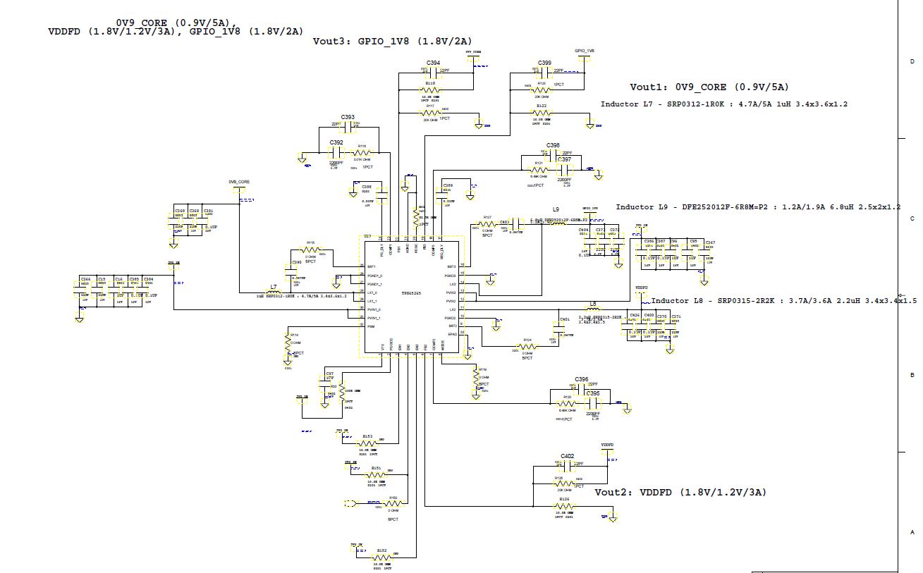
Original question:

Hi,
Can you pls review the attached section?
Vout1 - 0.9V/4A
Vout2 - 1.8V/3A
Vout3 - 1.8V/2A
Thanks!
