This thread has been locked.

If you have a related question, please click the "Ask a related question" button in the top right corner. The newly created question will be automatically linked to this question.

TPS62177: Catastrophic failure when 24VDC applied as VIN

Part Number: TPS62177

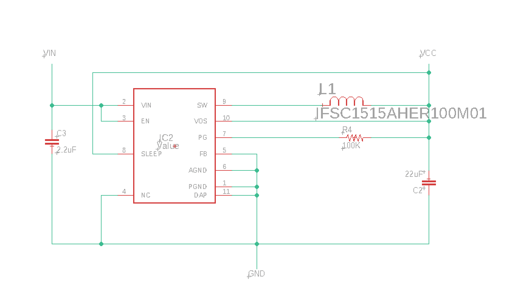
I am using the TPS62177 in a design where the input voltage is 24 VDC from a regulated power adapter (meanwell GS220A24). The maximum output current is about 250 mA @ 3.3V. I've used the standard design and component values from the datasheet: 2.2uF/50V input cap, 10uH/1.3A inductor, 22uF/6.3V output cap. In several cases it appears the TPS61277 device has stopped working or even exploded when the 24 VDC input voltage is applied or after some time of being powered on. This is a system consisting of about 200 modules, each containing a TPS62177, all connected to the same 24 VDC power source. I wonder if some side effect of all these buck-converters operating at the same time could cause input voltage ripple that would exceed the 28 VDC max rating? What else could cause this? I have managed to blow a hole in the TPS62177 by connecting a single board to a bench power supply, the only irregularity being that test wires bounced a bit on the terminal.

  • Hi  

    Could you share us the schematic and layout? Thanks.

  • Hi Vincent,

    Here is the schematic:

    And below is the part of the PCB with the regulator. The red pour (top layer) is VCC (output from regulator) the blue bottom layer is mainly a GND pour with some traversing data traces. GND is pulled up to the top layer with several vias.

    C2 is 22uF/6.3V, C3 is 2.2uF/50V, L1 is 10uH/1.3A, R4 is 100K (and probably not needed as I am not using the PG signal).

    The circuit works fine at 12VDC input. When I gradually increase the voltage to 24VDC it keeps working. But if I connect power with the voltage already set at 24VDC or rapidly disconnect/reconnect (like bouncing) input power I am able to fry the regulator (see hole in device in picture below) and sometimes also burn a hole in C3 or fry it completely (which should only be possible if the 50V voltage rating of that capacitor is exceeded). Voltage double checked, polarity double checked, and this has been happening on several separate setups (pretty much ruling out malfunctioning equipment).

  • Hi ,

    If you rapidly connect with 24V, it will have spike at input side, which exceed TPS62177 operating voltage. From layout side, I suggest to add 0.1uF ceramic close to VIN-GND pin.

  • Hi Vincent,

    I can definitely try adding a 0.1uF ceramic cap, but it seems pretty crazy that the spike would be able to fry the TPS (which has 30V absolute max rating on VIN) and the 50V rated input capacitor?

    I could use a lower input voltage, too, 12V for example, but would that leave me enough headroom vs. the max rating? I mean, if connecting a 24VDC PSU can cause a 50V+ spike, I suppose 12VDC could cause spikes of at least 2x that? ... which might then be within the rating.

    Also, I am curious as to the source of this spike. Is it due to the regulator, and the way it starts up? I have SLEEP tied to VOUT, and EN tied to VIN. Is that the correct approach?

    Thanks!

    Mads

  • Hi Mads,

    I think you can measure the input spike (with full bandwidth) to check how large the spike is, maybe start from 12V. Do you see the 50V input capacitor damage as well? My point is even 50V input capacitor is safe, but TPS62177 would be damaged because it only supports 28V.

    I don't think EN tied to VIN and SLEEP tied to VOUT could help solve the issue.

  • I reduced the input voltage to 12V and the issue appears to have been resolved. When using 24V input voltage I did in some cases see the 50V rated capacitor explode, as well as the TPS62177. In some cases it was just the regulator that burned a hole in itself. For future designs I'll add the 0.1uF cap on the input as you suggested.