This thread has been locked.

If you have a related question, please click the "Ask a related question" button in the top right corner. The newly created question will be automatically linked to this question.

LM5155-Q1: PSR flyback

Part Number: LM5155-Q1

Hi experts,

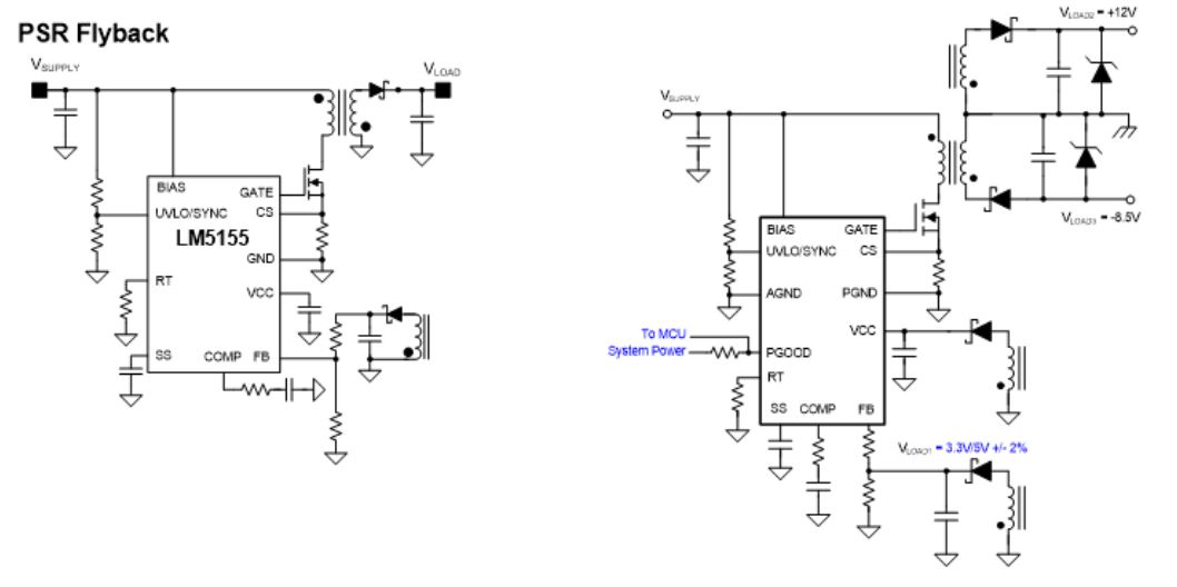
Below two circuits have some difference at FB pin design, I can understand the first one that the FB is connected in the middle of the resistor divider. But for the second one, I cannot understand why the FB is connected to the top of Rtop, could you please give some explanation? Thank you.

  • Hi Arie,

    Thank you for the catch.  Apparently it is an error when editing the figures.  I have notified our engineer and this will be corrected in the next datasheet revision.  I believe you agree that the resistor divider should be placed between the output rail and GND, and the  FB pin should be tied to the center joint of the divider.

    Thanks,

    Youhao Xi, Applications Engineering