This thread has been locked.

If you have a related question, please click the "Ask a related question" button in the top right corner. The newly created question will be automatically linked to this question.

TPS1HB16FQPWPRQ1 was damaged when the output shorted.

Other Parts Discussed in Thread: TPS1HB16-Q1

Hi Experts, we are using TPS1HB16FQPWPRQ1, but this part is easy to damaged when the output shorted, any suggestions?

  • Hello Leo,

    Welcome to E2E!

    The TPS1HB16-Q1 would only be damaged if being used outside of the datasheet parameters. It has built in protections that would protect it against over-current or over temperature conditions and prevent any physical damage to the device. 

    Would you be able to elaborate a bit more on your loading conditions? Specifically:

    1. What is your supply voltage?
    2. What is your steady state current?
    3. Are there any inductive/capacitive elements on the load?
    4. Do you have a schematic of how you connected the device?

  • Hi Timothy,

    Thanks for your prompt reply.

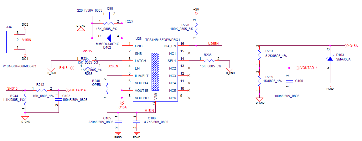
    We are using 16 pcs of TPS1HB16FQPWPRQ1 on one PCB, please see the schematic of one channel below, the supply voltage is 12VDC (DC1) or 24VDC (DC2) from lead acid battery (20AH).

    A MCU is used to monitor the current and voltage of every channel, also, the MCU is used to enable and disable every channel (the schematic below didn't show this, we can identify it based on the net name).

    We first connected a 12V 20AH battery then used a 10 cm long 16AWG wire to do a output short circuit test when the output was no-load, the result was 2 of the 16 chips (TPS1HB16FQPWPRQ1) were damaged.

    We also tested the output short circuit performance of this chip at 24VDC input condition, but 3 of the 16 chips were damaged.

    Should you have any questions, please let me know.

    Regards,

    Leo

  • Hello Leo,

    For the 24V case the device is not designed to be able to survive a short-circuit event. The device is designed for 12V automotive environments and a short-circuit at 24V at a high load current would likely damage the device. See the following excerpt from the datasheet:

    For the 12V case the device should not be damaged.

    Could you answer the following questions?

    • What is the extent of the damage? Is there physical damage on the device or does it just not turn on?
    • Do you happen to have any scope wave forms that show the input vs. output signal for turn-on and turn-off?
    • What is the method you are using to induce the short circuit? Are you shorting via hand with the cable?
    • What is the sequence/order here for the short? Are you applying the short after VBB/EN are high? Turning on into a short?

  • Hi Timothy,

    Regarding your questions:

    - Some chips are physically damaged and can't work (a burned hole on the surface of each chip) after the output is short-circuited.

    - We have observed the waveform of the damaged chip during short circuit, but unfortunately it has not been saved. When the chip is damaged, a current of about 20A flows through the chip for tens of milliseconds.

      If the chip is not damaged, the current during the short-circuit is only a few spikes and then the chip quickly turns off.

    - Yes, we are shorting via hand with the cable (length 10cm, 16AWG cable).

    - We did the output short circuit tests under the both sequences, and some of the chips were damaged.

    Regards,

    Leo

  • Leo,

    The first thing that sticks out here is,  "20A flows through the chip for tens of milliseconds".

    The device should start to regulate current and clamp off the device within a matter of microseconds. Anything in the millisecond range means that something is not functioning correctly.

    One thing I noticed in your schematic is that you have two different labeled ground, "D_GND" and "PGND". It looks like the input of the switch is connected to a different ground plane than the actual switch. Could you comment on the difference between these two grounds?

  • Hi Timothy,


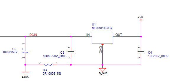
    The "D_GND" and PGND" are connected via a 0 Ohm resistor, please see below.

  • Leo,

    Got it on the ground planes. 

    From the schematic there is really nothing that stands out that is describing this behavior. The 24V short-to-ground makes sense since the device is rated for 12V nominally, however for the 12V the fact that you are getting amps of current going through the device for milliseconds points to something being wrong.

    Would you mind sharing the layout of how the device is mounted on the board? Specifically the ILIM pin between ILIM and VBB. If you are not comfortable posting it I can email you offline and work from there. 

    Any scope shots on turn-on and turn-off during non-damage events would help too. If there are any negative voltages on any of the pins this might explain what we are seeing. 

  • Hi Timothy,

    Could you please share your email address? I'd like to send you the PCB plot for review.

    Also, can TI improve the short circuit performance of this device to survive at 24V input voltage condition?

    Thanks,
    Leo

  • Leo,

    I sent an email to the address listed on your E2E profile. I will circle back to this thread once we find a root cause.