This thread has been locked.

If you have a related question, please click the "Ask a related question" button in the top right corner. The newly created question will be automatically linked to this question.

TPS56628: DC-DC Converter (TPS56628DDA) Problem

Part Number: TPS56628

Hello,

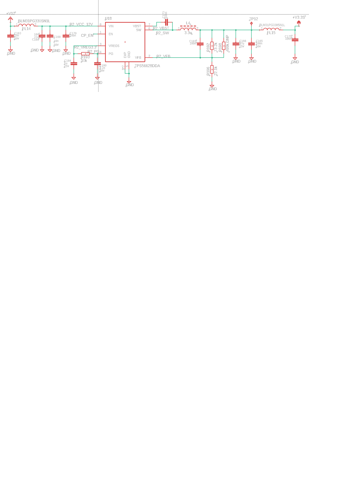
I am using TPS56628DDA for 5.5V and 3.3V Output. Output 5.5V is working. But I am not getting the 3.3V when I soldered other components on the bottom layer. for example LDO (3.3V to 1.8V). But top layer is working with components. But when I removed the components from bottom layer and I measured the voltage then it is showing 3.3V.

Can anyone help me out !!

Regards,

Rajat Barmon

  • Hi,

    The SCH is still not uploaded correctly.

    Please send me the SCH and layout through email, lishuang_zhao@ti.com.

    And I didn't understand your description clearly. Would you mind to clarify your test and debug method through email? For example, after soldering down which device (please write the part number), TPS56628 has 3.3Vout. With which device, it doesn't have output.

    Thanks,

    Lishuang

  • Hi Rajat,

    For the SCH review, where is the C183 100nF cap located? Bottom layer or top layer? C183 is working as feedforward cap, 100nF is too large. You can remove it and try again.

    If it can't help, please upload the layout or send the layout through email.

    Thanks,

    Lishuang

  • I am using C166 as a feedback path.... and regulator is in the bottom layer...... 

  • Hi Rajat,

    I am still confused about your first description "But I am not getting the 3.3V when I soldered other components on the bottom layer. for example LDO (3.3V to 1.8V). But top layer is working with components. But when I removed the components from bottom layer and I measured the voltage then it is showing 3.3V." 

    1. Where is your other components located? Where is LDO located? Remove this/these components, working? What components did you remove?

    2. What do you mean top layer is working with components?

    What's more,

    1. I can't see the FB trace on your uploaded layout. Is there any risk that FB is coupled or noised by the components you mentioned? 

    2. The yellow device in the middle of layout is a switch? Is there any risk coupled noise to FB?

    3. Can you remove C183 to try first?

    Thanks,

    Lishuang

  • Hello,

    I am using Same Chip three times (Output: 5V, 5V switched and 3.3V). I placed two converters (5V and 5V switched) on the top layer. Moreover, I am getting the output around 5.2V. 

    I placed other regulator on the Bottom layer (3.3V). and this voltage is also connected to LDO (Which will give us 1.8V ). Now my problem is without soldering the LDO part. I am getting the 3.3V to the input of LDO. and also getting 3.3V to other part of the components where i used the 3.3V. But when I mounted the LDO I am not getting the input of LDO and oviously i will not expect 1.8V from output of LDO. as LDO is not working. But in that state, I looked in the top layer's part are getting 3.3V where i used. 

    I checked the converter with load resistor. I am getting expected value. From this experiment I am sure my converter is working.  and also I have checked the footprint of the LDO. It is also ok. But I could not understand ,where is the problem?

    Reagrds,

    Rajat

  • Hi Rajat,

    From your description: "when I mounted the LDO I am not getting the input of LDO and obviously i will not expect 1.8V from output of LDO. as LDO is not working. But in that state, I looked in the top layer's part are getting 3.3V where i used. "

    It seems that 3.3V regulator worked since you can get the 3.3V where you used. But no input of LDO. There may be some issue with LDO or between regulator and LDO.

    So would you mind to check 3.3V regulator Vin, Vout and switching node waveforms when mounted LDO? According to waveforms, we can judge whether the issue is related to regulator or LDO. If regulator works well, we need to check LDO behavior.

    Thanks,

    Lishuang

  • Hello,

    I solved the problem. That was soldering problem of inductor. Pin 1 of inductor was not soldered Properly.

    Thank !

    Regards,

    Rajat

  • Hi Rajat,

    Glad to hear that the problem is solved. Thanks for feedback. 

    Thanks,

    Lishuang