This thread has been locked.

If you have a related question, please click the "Ask a related question" button in the top right corner. The newly created question will be automatically linked to this question.

TPS7A8300: CFF placement

Part Number: TPS7A8300

Hi team,

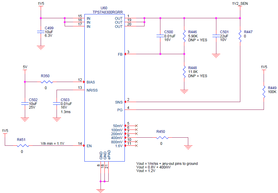
My customer is using the TPS7A8300 in ANY-OUT mode for a 1.2V output but now need to increase output from 1.2V to 1.3V. They need to use the feedback resistors instead of ANY-OUT mode by making the following changes:

  • Uninstall R450
  • Install R446 with a 7.5K resistor
  • Install R448 with a 12K resistor
  • Uninstall R447

Question - Since they have to disconnect SNS from OUT to get out of ANY-OUT mode and use feedback resistors, can they still leave C500 installed for the Cff?  I've always seen the feed forward cap from the output to the feedback pin, but datasheet is recommending the Cff be between SNS and FB instead of OUT and FB. Cff being between SNS and FB in ANY-OUT mode is essentially the same as having Cff between OUT and FB since SNS has to connect to OUT anyways. 

 Thanks,

Connie

  • Hi Connie. 

    You can definitely still use the FF cap as it will not affect if you are in ANY-OUT mode or regular operation mode. In addition, TPS7A8300 can provide a Vout of 1.3V using the ANY-OUT mode configuration. You can achieve this by grounding pins 6 and 9 (100mV and 400mV), and leaving the rest of the pins floating. Vout=Vref+(Sum ANY-OUT pins to GND), therefore, Vout = .8V+ (.1V+.4V) = 1.3V. 

    Regards,

    Edgar Acosta 

  • Hi Edgar,
    Unfortunately, we can't add wire jumpers to rework our boards to ground pin 6 for the extra 100mV so hopefully we can make this work with just BOM changes.  I want to make sure I understand the placement of Cff.
    ANY-OUT mode
    • Cff is recommended to be tied between FB and SNS
    • SNS is tied to OUT
    feedback resistor option
    • Cff is tied between OUT and FB instead of FB and SNS?  Is this ok or does it need to be tied between FB and SNS like the datasheet says?
    • SNS is left open
    Thanks,
    Joe
  • Hi Joe, 

    Yes you are correct in both cases.

    It is ok to connect the Cff between FB and OUT pins. I leave the following quote from the datasheet: "Although not required, a 10-nF feed-forward capacitor from FB to OUT (as close to the device as possible) is recommended for low-noise applications to maximize ac performance".

    SNS is to be connected only if ANY-OUT mode is required. 

    Sincerely, 

    Edgar Acosta