


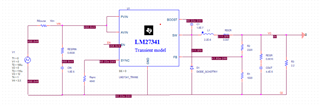
I am attempting to simulate the inverting configuration of the LM27341 buck regulator.
My goal is +3.3 V input, -9 V, 100 mA output.
However I am having trouble getting this configuration to simulate in PSpice for TI.
Even if I take the provided reference design and simply rename the ground node to "O2" and connect the ground symbol to what was the output pin, I see no output voltage developed in a transient simulation.
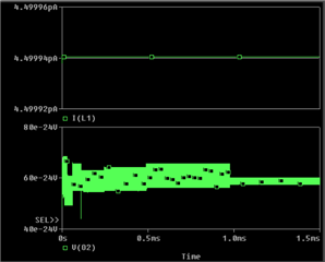
(Notice the scale of the inductor current is picoamps and the scale of the output voltage is 10x10^-24 V)
I believe this indicates there is an internal connection to the global ground node in the simulation model subcircuit that is producing unrealistic behavior.
Is there a way to simulate this IC in inverting configuration?
Thanks,
Matt

