


Other Parts Discussed in Thread: LM25085, LM5085
Hi,
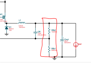
I designed in this chip to convert 18V to 12V at 8A. I used power designer which provided me with a feedback network of 10K and 806Ohms as shown.
If I used the equation in the datasheet:
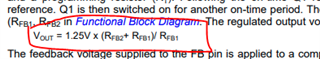
The output voltage should be 16.8V not 12. If I solve for Rfb1, in order to get 12V, I should have a 1.162K resistor. That is what I designed in thinking power designer has a bug. But the voltage is about 10V.
Above is my schematic and I don't used the C1, C2, R3 network for improved ripple and my output caps are ceramics. I do have considerable ripple (620mV) and when I tacked down a 100uF tantalum, the ripple decreased to about 320Ohm so it seems you need a little ESR to reduce the ripple but can you explain why the output voltage is way off?
Thanks!
John

