This thread has been locked.

If you have a related question, please click the "Ask a related question" button in the top right corner. The newly created question will be automatically linked to this question.

TPS650864: PMIC for xc7z007s

Part Number: TPS650864
Other Parts Discussed in Thread: TPS65023, TPS65916, TPS65917-Q1, TPS6521815, TPS650250

Hi,

my customer is using DA9062 to power xc7z007s from Xilinx.

I searched on our website and find TPS650864 suitable for artix7 Xilinx.

But I have several questions:

1. DA9062 can support 5V single input rail, but it seems that TPS650864 need a higher power rail, right? Do we have 5V input rail device?

2. If we still want to use TPS650864, do we need to program the OTP ourselves to make it compatible for the voltage level and power sequencing for xc7z007s or it's done in TI factory? If it's done by us, how to do it? Can we provide the file to be loaded to OTP and the software& hardware tool to do it? Customer says that DA9062 doesn't need their program to write registers and all are done before the device is shipped to them.

  • Hello,

    The TPS65086470 spin is designed for Artix 7 but you are correct that it is primarily designed for 12V input. Section 9.2.5 VIN 5-V Application in the datasheet covers how the PMIC can be utilized with a 5V input though using a small front-end boost. 

    Probably a better solution would be utilizing a hardware configurable PMIC like TPS65023. There's even a tech note about using it with Artix 7 here: https://e2e.ti.com/blogs_/b/powerhouse/posts/fpga-power-design-challenges-can-i-use-a-pmic-for-that

    Hope that helps!

  • Kevin,

    thank you.

    The customer has chosen TPS65916 to replace DA9062 since both of them are 5V input. And we have checked this device supply is relatively good.

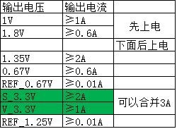
    And the power rail and current rating is okay, below is the configuration:

    1V and 1.8V need to be powered earlier, and then the rest could be powered(either simultaneously or one by one)

    The question is:

    1. Do we need to write the OTP for these power rail?

    2. Do we need to write the OTP for the power sequence?

    3. If yes, how can we do that? Is it done by TI factory or they have to change the OTP by themselves? If by themselves, do we provide the file to be loaded and the tool to program OTP?

  • Hi Howard,

    TPS65916 is not user programable. There are two released spins, TPS659162 (https://www.ti.com/lit/pdf/slvuao4) and TPS659163 (https://www.ti.com/lit/pdf/slvub99). There are also multiple TPS65917-Q1 spins that could be checked as well. Voltages can be changed after power up (as well as enabling and disabling) in the volatile memory, but the OTP and sequences are fixed.

  • TPS6521815 is user programmable as well, that may be worth looking into as well.

  • Kevin,

    thank you.

    Just curious, what's the point if voltages can only be changed after power up? If the original voltage is not suitable, then the processor could not be powered up, and then it's not possible to write the volatile memory to change the voltage. If the original voltage is suitable, then the processor could be powered up, and it's not needed to write the volatile memory.

  • Besides,

    what you recommended is out of stock in tiwebsite.

    So it seems that we can only rely on TPS65916 now.

    Since TPS65916 buck has feedback pin, so my understanding is that we can adjust the default output voltage through resistor divider, right?

    For example. for TPS659162, the default output voltage of SMPS1_VOLTAGE is 1.15V, if we use a 10k and 10k resistor divider and connect center tap of the resistor divider to the feedback pin of SMPS1, then we can get 2.3V output voltage, right?

  • Hi Howard,

    For the first question, it is not uncommon for systems to have multiple available I2C masters. For example, if the PMIC is on a peripheral board where there is a baseboard available that could support the I2C writes or if it's a system with a safety microcontroller. Certainly it does not apply to all cases.

    The primary use of the voltage changes in volatile memory is for the processor to voltage scale (i.e. start-up at a certain voltage and then adjust that voltage - https://www.ti.com/lit/pdf/slva646 for example). If it can be used for adjusting a part for a different processor, that's just fortunate. It seems in this case it cannot be.

    TPS65916 is not designed for use with an external resistor divider circuit. It has an internal resistor divider. I have seen customers utilize PMICs in the way described but the resistance has to be low (<10kΩ typically) to minimize errors and the buck performance may be impacted.

    Have you considered utilizing a couple smaller PMICs like TPS65023 + TPS650250 to replace the DA9062?