This thread has been locked.

If you have a related question, please click the "Ask a related question" button in the top right corner. The newly created question will be automatically linked to this question.

[FAQ]: Ideal Diode Controller or ORing Controller gate voltage is lower than expected

Part Number: LM74700-Q1
Other Parts Discussed in Thread: TPS2410, LM5051, LM7480-Q1, LM5050-1, LM5050-2, , LM7481-Q1, TPS2412

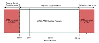
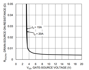
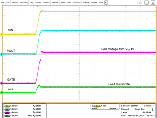
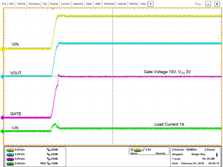
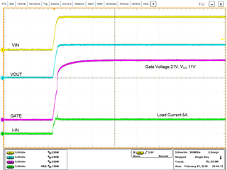
Gate voltage of Ideal Diode Controller or ORing Controller is low and the MOSFET is not fully enhanced.

RELATED PRODUCTS: LM74700-Q1, LM7480-Q1, LM7481-Q1, LM5050-1, LM5050-2, LM5051, TPS2410 and TPS2412

  • Background:
    Ideal Diode Controllers and ORing Controllers control the external N-Channel MOSFET in three different modes of operation as shown in Figure 1.

    Figure 1: Gate Drive Modes of Ideal Diode Controller LM74700-Q1
    During normal operation, controllers operate in regulated conduction mode or full conduction mode. In regulated conduction model, the linear regulation scheme maintains a very low forward voltage across the MOSFET source-drain. LM74700-Q1 regulates the forward drop across the MOSFET to 20mV (typical). LM5050-x and LM5051 regulated forward drop is 22mV (typical) and TPS2410/12 regulates to 10mV forward drop. Note that at higher load current, controller moves into full conduction mode and the MOSFET is fully enhanced.

    Answer:
    In linear regulation control, forward voltage of the MOSFET is regulated by controlling the gate voltage based on the load current. To be more precise, to regulate the forward voltage, the gate drive of the controller varies RDS (ON) of the MOSFET by controlling the VGS of the MOSFET.

    Linear Regulation Scheme:

    • IN-OUT > regulated forward voltage, increase VGS gate voltage, reduce RDS (ON) of MOSFET
    • IN-OUT < regulated forward voltage, reduce VGS gate voltage, increase RDS (ON) of MOSFET
    • IN-OUT > full conduction threshold, fully enhance the MOSFET with VGS gate voltage >10V
    • IN-OUT < reverse turn off threshold, turn off MOSFET by pulling GATE to SOURCE VGS = 0V.

    Let us take LM74700-Q1 for illustration of the linear regulation scheme. LM74700-Q1’s regulated forward voltage is 20mV, full conduction threshold is 50mV and reverse turn off threshold is -11mV.

    Forward transfer characteristic, i.e., VGS vs RDS (ON) of MOSFET DMT6007LFG is shown in Figure 2. At a nominal current of 3A, to regulate source-drain voltage to 20mV, controller need to maintain RDS (ON) = 20mV/3A = 6.67mΩ. From the forward transfer characteristic, RDS(ON) 6.67mΩ corresponds to VGS 4V and hence the controller regulates the VGS to 4V at 3A as shown in Figure 3.

    Next, at 1A load current, the controller need to maintain RDS (ON) = 20mV/1A = 20mΩ. RDS (ON) 20mΩ corresponds to VGS 3V and hence the controller regulates the VGS to 3V at 1A as shown in Figure 4.

    Lastly, at high load current 5A, the controller need to maintain RDS (ON) = 20mV/5A = 4mΩ. RDS (ON) 4mΩ corresponds to VGS >10V and hence the controller fully enhances the MOSFET with VGS to 11V as shown in Figure 5.

    Figure 2: Forward Transfer Characteristic of MOSFET DMT6007LFG Datasheet

    Figure 3: LM74700-Q1 driving DMT6007LFG at 3A Load Current

    Figure 4: LM74700-Q1 driving DMT6007LFG at 1A Load Current

    Figure 5: LM74700-Q1 driving DMT6007LFG at 5A Load Current