This thread has been locked.

If you have a related question, please click the "Ask a related question" button in the top right corner. The newly created question will be automatically linked to this question.

LM25118: LM25118

Part Number: LM25118
Other Parts Discussed in Thread: LM5176

Hi Team,

Please help on following question:

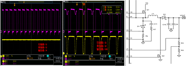
1. According to the data sheet, when the output is 12V, the input circuit of 17V and above will enter the BUCK mode, and the lower MOSFET Q2 will be turned off. In the actual debugging process of the DEMO board, 32V input is found. When 12V output, when the load is 3A, Q2 is turned off, and Q1 Turn on the BULK mode, but when the load drops to within 1A, the lower MOSFET Q2 will be turned on:

2. According to the data sheet, for example, from the high-voltage BULK mode to lower load, the high-end Q1 duty cycle continues to increase at this time. When the Q1 duty cycle reaches 75%, the IC will enter the BULK-BOOST mode, but start from the low-voltage BOOST mode How does the IC judge whether to enter the BULK-BOOST mode when boosting is not detailed in the specification, please help explain.

3.There is no OVP protection function in LM25118, can you help me recommend other T1 buck-boost ICs with OVP function or any good suggestions to go to the external line for OVP protection (for example, which PIN is better for comparison and protection)

4. There is no external OTP protection function in the LM25118, only the built-in OTP function of the IC, and the protection temperature is as high as 165°C, which cannot effectively protect the power MOSFET and inductors from over-temperature. Can you help recommend other T1 buck-boost ICs with OTP function or Is there any good suggestion to go to the external line for OTP protection (for example, which PIN is better for comparison and protection).

Thanks and best regards,

Jamie

  • Hello Jamie,

    Thank you for having a look at this device.

    1. I do not understand which question you have here.

    2. The device has a buck mode and a buck-boost mode, no pure boost mode.

    3. What are the requirements of the application?

    4. We do not have a buck-boost device with external over-temperature function. You would need to add this feature externally.

    Best regards,
    Brigitte

  • Hi Brigitte.

    1. I do not understand which question you have here.
    The Q2 will turn off in buck mode but found LM25118 EVM the Q2 turn on in 32Vin /12Vout /1A.

    2. The device has a buck mode and a buck-boost mode, no pure boost mode.
    Could you provide any date about LM25118 from the buck mode transform to the buck-boost mode?

    3. What are the requirements of the application?
    Customers need OVP function about 110%Vout~120%Vout for their end customer needs

    4. We do not have a buck-boost device with an external over-temperature function. You would need to add this feature externally.
    Which PIN of LM25118 can add NTC resistor for OTP function

    Thanks and regards

  • Hello Rock,

    1. This looks like DCM, not buck-boost mode. Please measure in addition the switch nodes.

    2. The transition depends on the duty cycle in buck mode as well as the voltage ratio on pins VIN and VOUT. Figure 10 in the datasheet shows the HO and LO duty cycles over VIN for a 12V output.

    3. For OVP, please check the supervisor ICs: https://www.ti.com/power-management/supervisor-reset-ic/overview.html
    A
    nother possibility would be to use LM5176 which is a buck-boost converter with a PGOOD output for UVP and OVP.

    4. There is no pin that could implement OTP with an external NTC.

    Best regards,
    Brigitte