This thread has been locked.

If you have a related question, please click the "Ask a related question" button in the top right corner. The newly created question will be automatically linked to this question.

ISO5452: ISO5452

Part Number: ISO5452

HI T.I Support,

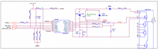
1 - I use the ISO5452 as DESAT protection on IGBT. The IGBT have  VCE=5V in 300A and on this current I want to protect. Please advise how to set the application to 9V - (DESAT threshold).

     Can I add a Zener diode in serial ?   What Part Number of diode  (assume 500uA from pin DESAT flow through the Zener diode) ?.

2 - As I see in the user manual you put resistor of 10 ohm in serial to VCC1 (pin15).   (Figure 54).

     Please advise why 10 ohm ?.    If I put 1 ohm - is it a mistake?  What can happened?

Thank you

AVNER

  • Avner,

    - I use the ISO5452 as DESAT protection on IGBT. The IGBT have  VCE=5V in 300A and on this current I want to protect. Please advise how to set the application to 9V - (DESAT threshold).

         Can I add a Zener diode in serial ?   What Part Number of diode  (assume 500uA from pin DESAT flow through the Zener diode) ?.

    Yes you can, and this is a common Practice to raise the equivalent DESAT threshold. The key spec to care about for Zener diode is the power rating (in mW) and the VZ zener voltage.

    mW rating we would need si 500uA*(9V-VCE(typ)), which is actually really low so pretty much any small package zener can work here.

    Normally, 1-2 schottky or PN diode is in series to block the high voltage at the drain/collector lowering the desat threshold by V_DESAT-n*VF, where n is how many you have in series, which like you said you can compensate for by adding the zener voltage and it becomes V_DESAT-n*VF+VZ.

    As far as part recommendations, I can't give an exact one that we have used in reference designs, but zener are available at 100mW rating which is more than enough, and you can look for a 2-3V zener which are common at this power rating. Any one should be good since the power dissipation would be so low

    https://www.digikey.com/en/products/filter/diodes-zener-single/287?s=N4IgjCBcoJwEwAYqgMZQGYEMA2BnApgDQgD2UA2iHAAQBqIxcAdDfY0wCx0NVMDs3YgGZBIIUxH0AusQAOAFyggAqgDsAlvIDy6ALL5MuAK4AnfCAC%2BjMAhjIQaSFjxFSFcAgTUAtgHUQMiAKSmqaOvqGpuYWVlTuAF74qvgm1AAm6iRp5lIWQA

    2 - As I see in the user manual you put resistor of 10 ohm in serial to VCC1 (pin15).   (Figure 54).

         Please advise why 10 ohm ?.    If I put 1 ohm - is it a mistake?  What can happened?

    I'm not exactly sure but the purpose is one of 2 things (possibly both).

    #1 Current limiting in case primary-side VCC1 goes into a dead short, though usually we see this on secondary side so I think its probably #2.

    #2 It also would have an RC effect with the decoupling caps, so it could also be useful for attenuating switching noise on VCC1.

    If this answers your questions please let me know by clicking the green button, and let me know if you have any other questions.

    Best

    Dimitri