This thread has been locked.

If you have a related question, please click the "Ask a related question" button in the top right corner. The newly created question will be automatically linked to this question.

TPS62913: +/- 4.75V inverting low noise power supply

Part Number: TPS62913

Hi,

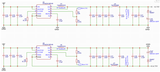
I'm looking for some assistance to create a +/- 4.75V low noise suply from 6V input and also optimise transient performance.

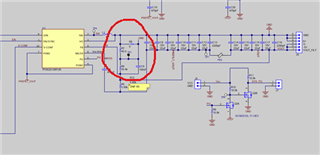
Can I use the TPS62913 to create a negative supply similar to SLVA317B?  If so how would I connect the TPS62913 for negative rail?

  • The TPS62913 can be used as an inverting buck boost for a quiet output rail.  There are a few items to consider:

    1. The output configuration is similar to other buck converters used in an inverting buck boost configuration, so the same limitations apply such as reduced output current, limitations on input to output voltage based on input voltage tolerance, and compensating for the right half plane zero (RHPZ).

    2. The output current limitation is based on the input and output voltage, and is summarized in the table below.

    3. The TPS62913 has internal compensation, so it is not possible to adjust the compensation to avoid the RHPZ.  The only way to reduce the crossover frequency is to add output capacitance. 

    4. Since the device is referenced to the negative output voltage, logic must be used on the EN pin to pull is to -VOUT to disable the part.  Additionally, the PG signal must be level shifted using external logic as shown in the schematic below. 

    5. The TPS62913 has ferrite bead compensation, and the placement of the ferrite bead for optimal ripple reduction is on the negative output rail as shown below. This schematic is for a -5V output, and should be very close to your application.  This design is being finalized and will be made available as an evaluation module.

    6. An additional app note you may want to read now is https://www.ti.com/lit/an/snva856a/snva856a.pdf.  The schematic above does not use a capacitor from input to output, and is reliant on a very tight layout to accomplish a similar function. However, it may be an option to consider. Below is the layout for the above schematic. This is still an engineering design, and may not be the final layout used in the released EVM.

    In summary, the TPS62913 is a good choice for creating a low noise and low ripple inverting buck boost design, as long as it meets the output current requirements and you don't have significant load transients with tight response requirements. 

  • Thanks Steve!  I believe I am almost there...

    Although I am not exactly certain what the schematic circled in red is up to.  Can you provide a higher res shot?

  • Yes, you are close, although you swapped your R5 and R6 resistor values which should not be done.  The area in red is similar to the standard EVM to provide an option to break the loop for stability measurements.

  • Please confirm this answers your question.