This thread has been locked.

If you have a related question, please click the "Ask a related question" button in the top right corner. The newly created question will be automatically linked to this question.

Multiphase converter using UCD9224 and UCD74111 :Issues

Other Parts Discussed in Thread: UCD74111, UCD9224

Hi

We are facing some problems with our multi phase converter using UCD9224 and UCD74111. Please answer my queries below:

The specs of the converter are : . 12V to 1V @ 48 A (SoC requires only 40A),  4 phases at switching frequency of 700KHz, c. No phase shedding at low loads,. Current sensed using 2mOhm sense resistor, 1V Enabled using the the seq1 pin (Active High) and stay on dependency also on  seq1 pin (Active High)

configuration file : Attached


The issues are:

  1. Problem we are facing is that the Seq1 input is not responding to every other pulse, so we have to toggle the seq1 pin two times to get the rail On. Note that the first time after each power on the rail turns on when seq1 goes high. Once the rail is ON , then if you want to power cycle the rail you need to  apply two pulses. (The power supply is configured to turn on when pin 21 (SEQ 1) is high. We have set the Turn on dependency and Stay on dependency as Pin 21 (Active High ) . Why does the seq1 pin behave so?
  2. We found that the rail sometimes switch off abruptly (although currently the rail is not even loaded to 5% ). It reports a MFR fault , and in the status page it shows a FLT fault.  We checked the FLT  pins after rail went down,  FLT o/ps of all UCD74111 were low.  What could be the possible casue for a FLT fault. Also please let me know where can I find the description of each error mentioned in the status page of the Fusion designer?
  3. Although we don’t know the cause for abrupt FLT faults. We  noticed that this FLT fault can be triggered by switching off the SEQ1 pin. Is that expected? We think the Seq1 input is stable even when the above mentioned abrupt FLT faults were observed

 Thank You

Ashok

  • Hello Brad,

    Please give your suggestion on the load regulation problem that we are seeing on our design . 

    Problem :

    1. The load regulation of the 1V rail is not very good. When measured at very low load (1A) the o/p is 1.0 V. However      as soon as the processor is out of reset the load increases to 13 A  (still only25%of max current) we see that the 1V rail drops to 0.9V
    2. Note that we have a remote sense directly connected to the voltage sense pins of the SoC, and we confirmed that the drop in voltage is reflected in the EAP1+/-.
    3. I have tried couple of things to solve the problem but didn’t help solve the poor regulation:
      1. Tried the calibration tool in Fusion designer : It always gave an error at the end (pls see log attached) , although it did adjust the VOUT_CAL_OFFSET which resulted in a higher voltage at low load. So the voltage goes to 1.1V at no load and falls back to 1.0v at 25% load. But this is not an acceptable solution as the SoC that powers the rail normally operates only upto 1.050V.
      2. Tried adjusting the voltage divider on the EAP+/- lines thinking that it is somehow saturating the error amp. I tried ratios of 0.9, and 0.8  and made the same changes in fusion designer to adjust the gain values. I observed that the voltage output goes upto 1.180 V at no load when ratio is 0.8. Again, when the loaded to 25% of max load , voltage droops by 100mV.
      3. I tried the frequency response measurement of the power section using the fusion designer option. I noticed that the rail voltage becomes exact 1V after the measurement (even at 25% load) , not sure why. Is it because of the 25 mV noise added? Any way , even though I save the measured response to the hardware, once I power cycle the board the poor load regulation comes back

    Initial reply from TI :

    I’m going to start with the second problem about the load regulation because I think we are close to an answer.  You mentioned using a remote sense which can lead to an undesirable loop response.  The frequency response measurement (AKA Auto-ID) can improve this by calculating the open-loop transfer function from a synthesized sine wave.   It appears the poor load regulation is due to the remoteness of the sense, and the Auto-ID is the way to correct for this.    As for why the poor regulation returns after power cycle, this is likely because the same config file was loaded onto the controller.  From the end of the Calibration Log:


    "VOUT_CAL_MONITOR [Rail #1]: was 0.000 V, now 0.017 V"

    “VOUT_CAL_OFFSET [Rail #1]: was 0.000 V, now 0.168 V"


    In the configuration file:


    VOUT_CAL_MONITOR = .015 V

    VOUT_CAL_OFFSET        = .045 V


    Update the values in the config file with those from the calibration, and this issue should go away. 

    Additional Tests and Results : The problem persist

    The second issue that I marked in red is a more pressing issue. I see that the load regulation problem persists even though I save the Auto ID data

    The discrepancy in the  VOUT_CAL_MONITOR, VOUT_CAL_OFFSET   that was pointed out in last email was just because those files were from two different configuration files . However, you will notice that configuration file does have the measured data. Also, I don’t believe adjusting VOUT_CAL_OFFSET   by 168 mV is an option for us , that will results in very high voltage at low loads !!. We would like to improve the load regulation on this rail.

     I reconfirmed the results by running Auto-ID and Writing the results to the Flash and also saving the project file (attached). Then I power cycled the board and then did a comparison between the device parameters and the saved project file. You will notice that all the compensation and gain parameters are same, but the voltage drops by 100mV for a similar load (see attached .xls file)

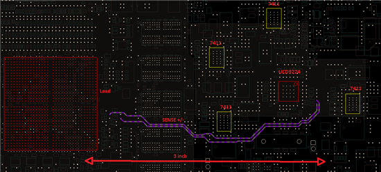
     Also attached is a pic showing the placement of the components on the board. Let me know you thoughts on it

     Did you mean that it better not to use the remote sense on the UCD 9224? How can we achieve better load regulation. Please let us know you suggestions to improve the load regulation.


     4774.UCD9224 Project_4phase_1_aug30_no_flt_1A_2A_AutoID.xml

    4617.Device Configuration Comparison.xls

    Thank You

    Ashok

  • Your issues with regulation are probably more related to layout than configuration although loop response can be a source as well.

    Is there any decoupling at the source of your feedback lines by the load?

    The feedback lines run quite close to one of the UCD74111 devices and under what could be the output inductor but I don't know what layers all these devices/traces are located.  The length of feedback between the load and the controller is not the issue, I've seen designs that have feedback traces more than 4x longer with much better load regulation.

    I see you have filtered the V33A rail feeding the controller, this will help prevent andy noise on the main V33 rail from affecting the analog section of the controller, is your decoupling for the controller tightly coupled to the device? 


    You could try flying leads to jumper the feedback lines, lifting the resistors to isolate the trace through the board to see if this helps.


  • Thank You for the suggestion  Brad,

    I tried adding a short jumper for the feedback trace after disconnecting feedback lines in the pcb. However, the 1V rail voltage dips by atleast 70mV when a 25% of the max load (approx 13A) is applied. This is the same behaviour that we see with the remote sense.

    I also monitored the EAp/EAn line at the controller using a diff probe. I found it to be clean after the filter 1K series and 680pF,100K shunt (1K is split into 500Ohm on each line). There is no filtering at the source , its connected to the volt sense pins on the SoC. Also, I do see the feedback signal voltage drop down by the same amount when load kicks in.

    The drop in voltage is also reported by the TI fusion monitor if the programmer is connected. So the controller is seeing the dip in the rail voltage , but doesnot compensate for it . Not sure why

    Please let me know your suggestion

    Ashok