This thread has been locked.

If you have a related question, please click the "Ask a related question" button in the top right corner. The newly created question will be automatically linked to this question.

TPS3897 - To monitor 5V

Other Parts Discussed in Thread: TPS3897, TPS3895, TPS3898

Hello , 

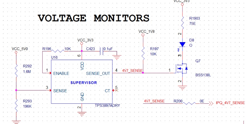
We have used TPS3897 in our design to monitor 5V power supply.

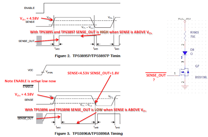
We have used the open drain part  , if the voltage drops below 4.5V we need to indicate the status through the LED and the same signal is connected to GPIO of 1.8V tolerant.

Theory of operation if the voltage is above the 0.5V  the output is low , that means the transistor will not conduct , if the reference voltage drop below the 0.5V the output will be high and the open drain output is pulled high and the transistor starts conducting and the 1.8V I/O is pulled high.

Can you please check and tell us our understating is correct

Thanks 

Antony 

  • HI Antony,

    If my understanding is correct, your logic is reversed. You have the Sense threshold set to 4.58V. With the TPS3897, The SENSE_OUT is low until SENSE rises above the threshold. So if VCC_5V0 is present the LED will be on. (Note: By on, the VGS of the BSS138L will be above VTH but the drain current may be limited to less than 100mA. not sure if this is enough for your LED or not). NOTE: RDSON in this region is not defined on the datasheet.


    If my understanding of your intended function is correct, you want the LED on when VCC_5V0 is not present, So there are two options:

    1. Invert the SENSE_OUT

    2. Use the TPS3898A

    I hope this helps.

    Regards,

  • Hi John ,

    Thanks for your review.

    Here is my understanding

    (I think N-Channel MOSFET is switch ON if the voltage is present at the gate input ).

    The internal threshold of the TPS3897 is (500mV) , We have set the threshold to (537mV) if 5V is present . So , if 5V is present the sense output will be low .So, the N-Channel MOSFET is switched off and the LED won't glow.

    If the 5V drops to 4.5V then the threshold will be (0.474mV) , then sense output will be pull-up to 1.8V and the MOSFET will turn ON and the LED will glow.

    Please advice ...

    Regards
    Antony
  • HI Antony,

    I think the delay in the timing diagram may be causing confusion. Since you are not adding a delay capacitor, the delay will be minimal. The odd numbered devices TPS3895 and TPS3897 would have SENSE_OUT HIGH 5V is present. The even numbered devices would have SENSE_OUT LOW if 5V is present. I attempted to make it clearer below. Also, to enable the odd numbered devices, the enable would now be connected to GND.

    I hope this helps.

    Regards,

  • Hi John ,

    Thanks again for the detailed explanation

    We can replace the N- Channel MOSFET with P-Channel MOSFET- I hope this will resolve the issue.

    Appreciate your support here

    Regards
    Antony
  • HI Antony,

    OK, but you probably need to move the P-channel FET above the resistor and Diode and change the SENSE_OUT pull_up to VCC_ 3V3.

    Regards,
  • John,

    okay , but we need to give the SENSEOUT to 1.8V tolerant GPIO as a interrupt , we may not pull -up to 3.3V is that okay ?

    Regards
    Antony
  • John ,

    How can we  determine the  sinking current  by the  SENSE_OUT pin ? for the TPS3897 device.

    Our LED required 20mA forward current  .

    Here is the schematics

    Regards

    Antony 

  • Hi ,

    In our current design , we are planning to use TPS3897 for voltage monitoring(5V).

    we have connected LED at the open-drain output and a FET based level translator that is connected to the interrupt pin of the processor.

    We would like to know what is the maximum sink current for the RESETOUT_PIN.

    Posted our schematics  , Please advice 

    Thanks 

    Antony 

  • Hi Antony,

    Please note that the Abs Max current for SENSE_OUT is 10mA.  The recommended current is 1mA.

    Very Respectfully,

    Ryan

  • Hi Ryan,

    Thanks !!

    I'm just be curious about the recommend current is 1mA and the Absolute maximum is 10mA.

    Our LED can sink 10mA of current ! , if that is the case which value do i need to consider for design ( Recommended (Will not work ) or (Absolute Max ) Will work.

    Regards

    Antony 

  • Hi Antony,

    Absolute Maximum ratings are stress ratings only. The device is not intended to operate at those levels. When designing with any integrated circuit it is important to ensure that your design remains within the recommended operating conditions for proper functionality. Unfortunately it seems that TPS3897 is unable to satisfy your design requirements in your latest configuration due to current.

    I believe that your original schematic structure will work, but there seems to be confusion on the output logic. I see that you have two "actions" that will be triggered by SENSEOUT. You have an LED that will turn on/off and an input to your processor. In order to ensure that you have the correct output logic, I have two questions:

    1) do you want the processor input to be high when the LED is on or when the LED is off?

    2) it appears that you want the LED on when SENSE is low such as a "power bad" indicator. Is this understanding correct?

    I believe that John's understanding is that you want the input to the LED to be on when the SENSE is low. This would require TPS3898 which is pin to pin with TPS3897. The difference is the output logic of the two devices. Using your initial schematic with TPS3898, when SENSE is low, your LED would be on and the input to your processor would be high. When SENSE is high, your LED would be off and the input to your processor would be low.

    Very Respectfully,
    Ryan
  • Hi Rayan,

    Thanks for understanding our requirements.

    From the TI product portfolio there are many voltage monitors that can support +/- 20mA sink current, but unfortunately we need to stick to this part (TPS3897)

    John helps us understanding the difference between TPS3897 and TPS3898.

    If the monitoring voltage drops below the threshold (500mV) – TPS3897 gives low output and TPS3898 give high output.

    1)    do you want the processor input to be high when the LED is on or when the LED is off?

    The processor which we are using is 1.8V GPIO and we configured that as interrupt, by default this should be high, if voltage drops below the threshold it should be driven low.

    So, we need the processor input to be low when the LED is on

    2)    it appears that you want the LED on when SENSE is low such as a "power bad" indicator. Is this understanding correct?

    Yes, correct

    We plan to use the original schematics structure by using the same part TPS3897 with p-channel mosfet instead of n-channel , when the sense input is above the threshold the output is pulled-up to 1.8V which is connected to the gate of the p-channels mosfet and the same is given to processor GPIO (Which high by default) and P-channel mosfet is switched off and the LED is off.

    If the voltage drops below the threshold the output will be low, this makes the GPIO low and P-Channel mosfet will start conduct and the LED is on.

    Here is the schematics, please note we will replace the N-Channel BSS138L with P-Channel NDS0605 and we have selected the 1.8V led with 20mA forward current .


    Regards

    Antony

  • Hi Antony,

    Thank you for clarifying your application! It looks like you found a way to make everything work.

    Very Respectfully,
    Ryan