This thread has been locked.
If you have a related question, please click the "Ask a related question" button in the top right corner. The newly created question will be automatically linked to this question.
Hi
I am using a typical Chinese DC-DC converter (constant current) 250W assembled on a metal core laminate to drive some string leds.
The configuration is : input : 12 VDC - 2,5A - Output 25V- 1,2A - total 30W. I firstly used 10 samples to submit 2 month test and they worked well.
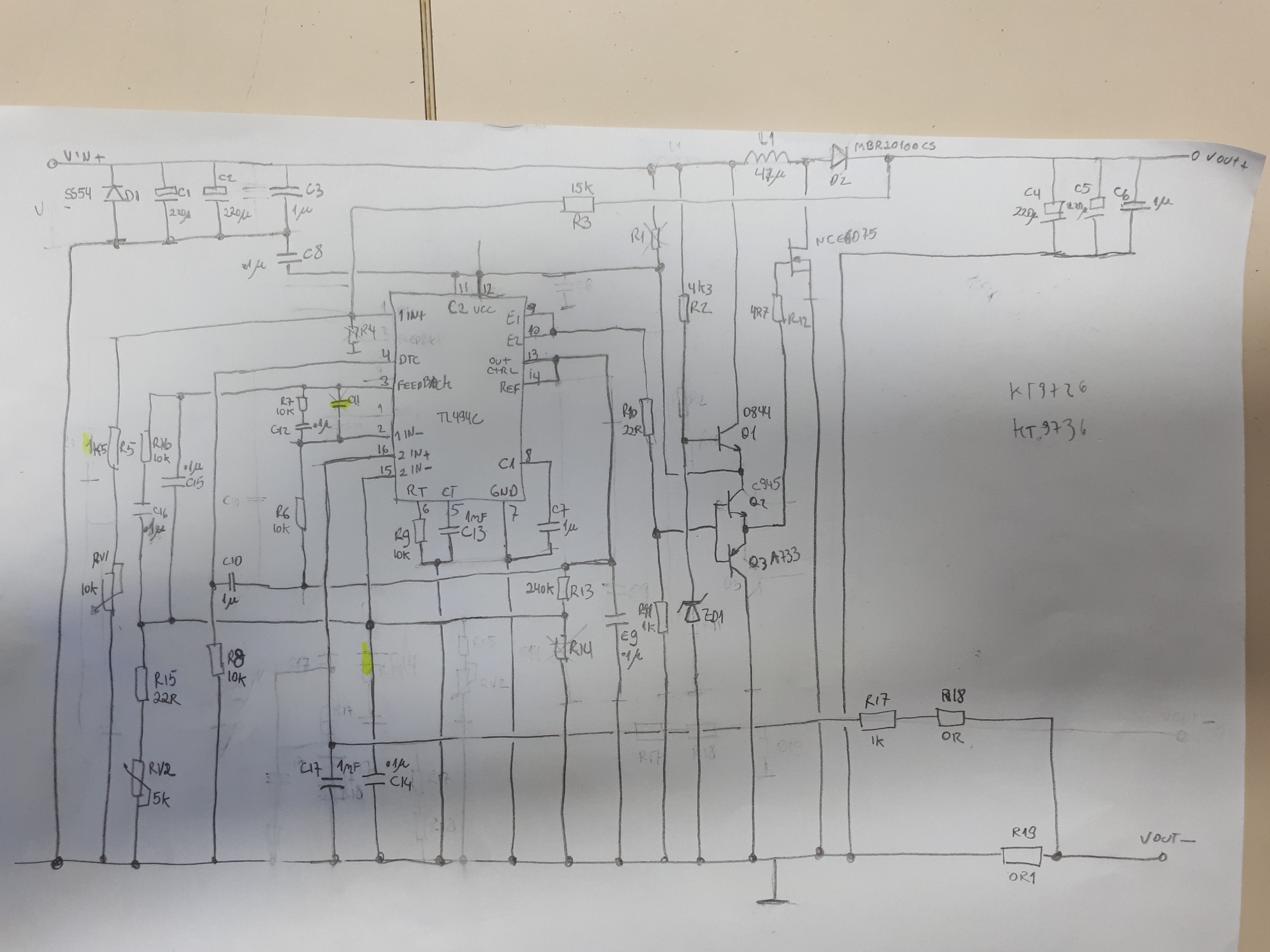
Now I have a customer order of 1000 pcs and ordered the dc-dc converters direct from china. The module is based on TL 494 with 2 tripots for output current and voltage adjust.
When I started testing the product, I noticed all the batch is producing a peak of current when I turn on the PS. Such peak of current , when adjusted for 12V input, occurs for around 0,5 seconds during startupand the system returns to the voltage and current previously adjusted. If i reduce the input voltage to less than 11VDC, the peak occurs but the system does not return to adjusted values, As result, the pcb increses the temperature and will fattaly burn the module.
I replaced the TL 494 bey new ones and notices the modules became muc,much more stable, but I still notice a little peak of current in voltages lower than 12V. In this case , it is only a start up peak and the circuit starts working. I claerly noticed there is something wrong with the original TL494 that came with the batch. Has anyone experienced such problem already? Is it the TL494 the responsible for such peak , or could be a deffective capacitor of the typical application?
Hi John
Both are package soic 16. Despite the operation temperature I did not see any difference. Why did you say TL494C part will not fit on a TL494 pad. In practice, all modules of this manufacturer came with TL494 and in all modules there is a same behavior: peak of current when stat up the module. I purchased two modules of different manufacturer . Both came with TL494 C and both worked. I replaced the tl494 by a tl494c in the module with strange bahavior, and it started working.
please see the pictures below. TL494C works, TL494, which came with the module doesnot work. Perhaps the TL 494 can be conterfeit as you mentioned .
Hi John
Sorry to insist in asking you support. I ordered new TL494-C and replaced all from the 600 pcs I bought . Most of them are working properly, but I still have this peak of current when startup the module. I noticed a better behavior , howeverÇ
1- some modules still present the peak of current ,,but 100% return to the adjusted numbers
2- the module specs are shown below, the moduel was designed to work from 10VDC input on, but this peak occurs around 11,5VDC input.
Unfortunately I do not have the electric diagram to make a better analysis, so if anyone have it and could make it available, I would be thankfull.
Module name: 250W constant current module
【Module Properties】: Non-isolated boost module (BOOST)
【Input Voltage】: DC8.5V-48V
【Input current】: 10A (MAX) More than 8A Please strengthen the heat dissipation
[Static working current]: 10mA (12V to 20V, the higher the output voltage static current will increase)
【Output Voltage】: 10-50V continuously adjustable
12-80V fixed output (for bulk customers)
【Output current】: 10A MAX more than 6A Please strengthen the heat dissipation (with the input and output pressure, the greater the pressure difference, the smaller the output current)
【Constant current range】: 0.2-8A
【Output Power】: = input voltage * 10A, such as: input 12V * 5A = 60W, input 24V * 5A = 120W,
Input 36V * 5A = 180W, input 48V * 5A = 240W,
For more power, you can use two modules in parallel, such as the output to 10A, you can use two modules in parallel,
Turn the current of each module to 5A.
【Operating temperature】: -40 ~ + 85 ℃ (Please strengthen
the heat when the ambient temperature is too high)
【Working frequency】: 150KHz
【 Conversion efficiency 】 : 96% high (efficiency and input, output voltage, current, pressure-related)
Over current protection: Yes (input over 13A, automatically reduce the output voltage, a range of errors.)
【Input reverse connection protection】: Yes, (less than 5A, if
you need more reverse current, please input string into the diode)
[Installation]: 4 3mm screw holes
【Wiring】: wiring output
【Module Size】: Length 70mm Width 36mm Height 13mm
【Single module】: 50 grams
Hi John
I finaly decided to get the electric diagram by using reengineering way. I firstly removed the layer from the aluminium and made a negative of the layout. As result i could re-draw the circuit. I measured the capacitor values and the diagram was finaly in hands. Analysing it and the documentation you recomended , I modified the soft start circuit, changing c10 to 10UF and R8 to 100k. The startup is very slow(around 0,5s) and the peak doesnot hapen anymore . As I am using the module as source to led strings, I do not see any problem if the start up occurs slowly. Do you see problem if I configura the soft start to around 0,5s instead the recomended 50-100 cycles of clock:? If not , my problem is solved. Please see the diagram below: