This thread has been locked.

If you have a related question, please click the "Ask a related question" button in the top right corner. The newly created question will be automatically linked to this question.

ISO5451: Wrong turn-off signals

Part Number: ISO5451

Hi,

For a full bridge I have been designing gatedrivers using TI ISO5451.

To get to see how the whole system works I did built up a small system with only one IGBT just for testing purpose:

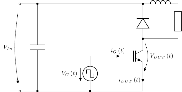
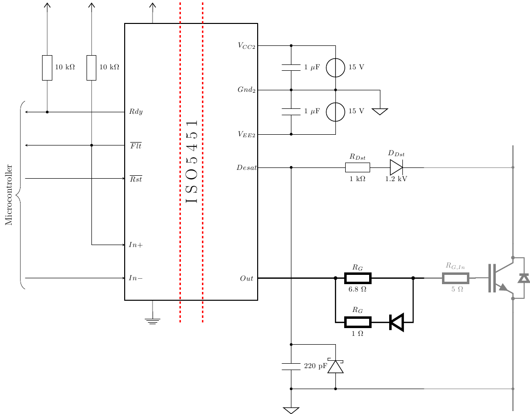
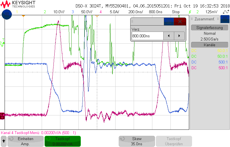
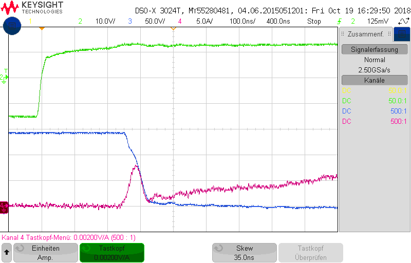
First everything worked quite well. But after increasing input voltage to approximately 120 volts, the gate driver starts to shut down the IGBT shortly after the on-state has been reached, as you can see in the next picture (working voltage will be 560 volts, the IGBT has a rated voltage of 1200 volts).

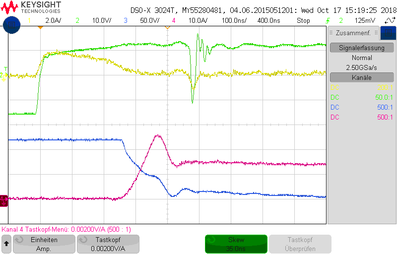
Yellow: Gate Current          Green: ISO5451 output voltage          Blue: IGBT voltage          Pink: IGBT current

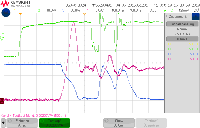
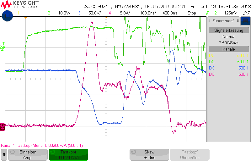
When increasing input voltage even more, sometimes several turn-offs do appear at the gatedriver, the fault is repeating itself.

I have already tried the following steps:

- Shorten DESAT-protection to the emitter to avoid influences of the desat protection, the problem still exists

- Try a different gatedriver did not change anything

- Increase blocking capacity at the input of the gate driver which only slightly shifts the voltage at which the effect starts to appear

- Reduce or increase the gate resistor, no effect could be observed

- Remove load inductance (turn on at zero amps), this allows the IGBT to turn off faster and avoids the problem

- Increase the capacity of the 220 pF capacitor at desat protection

- Measuring at the input of ISO5451: Neither IN nor FLT indicate the turn-off

Actually the problem does not effect the final application as we will turn on zero current. Otherwise I still would like to know the cause of this problem and probably change my design to avoid further problems.

Best regards,

Yanick

  • Hi Yanick,

    1. Can you share the schematic of the gate driver circuits?

    2. In the experimental waveform you have shared, the gate voltage dips however there is the IGBT did not turn off as the VCE voltage is till high. Can you also share a waveform where the IGBT actually turns off?

    3. In your setup, the current should ramp from zero when the IGBT is turned on. In your waveform, the current is at around 15A. Are you showing the second pulse of double pulse testing? 

    4. The IGBT you have used is discrete of a module? What is the package? The gate voltage dip may be caused by common emitter inductance. Can you also share the layout of the gate driver circuits showing connection to IGBT? 

    With Regards,

    Xiong

  • Hi Xiong

    Thanks for your fast reply.

    1. The schematic looks as follows:

    For testing purpose I also made a connection between the DESAT-pin and the emitter.

    2. First example: The gate-driver tries to turn off only for a short time:

    Second example: Turning off wrongly with some oscillation:

    Third example: Turning off completely but after a short time turn on again:

    3. I was turning on onto an inductive current, showing the steady state of a buck converter. But this is the same as the second pulse of the test. The first pulse doesn't trigger an error, as you can see in the picture:

    4. The module I use is called SKM100GB125DN by Semikron. The gate-driver is connected by short leads (twisted, length approx. 2cm). The layout of the gate-driver looks as follows:

    Front

    Bottom

    Kind regards,

    Yanick

  • Hi Yanick,

    Thanks for the info. I will have offline conversation with you for more efficient discussions. With that, I am closing this thread.

    With Regards,
    Xiong