Hello team,
Please see below customer question:
Our products are currently powered up by a Lead-acid battery, and the charge controller we use is the BQ24650. We used as reference the slva437a document to use this charge controller with lead-acid batteries. However we've had some trouble with our charge controllers, some of the shunt resistors are burning even though they are oversized. Also in some cases we even have to replace the BQ24650 itself and after some minutes it burns again.
Initially we had a 1/2 watt R17 resistor, but as this started to happen and after we analyzed the circuit we decided to change it to a 2 watt resistor
To find the shorts/hot spots we tried the test with the current limited power supply and battery or resistor in series and ran it on a burned board:
PH pin to ground has 5M ohms to ground.
SRP pin to ground has 5M ohms to ground.
D1OUT has 1M ohm to ground.
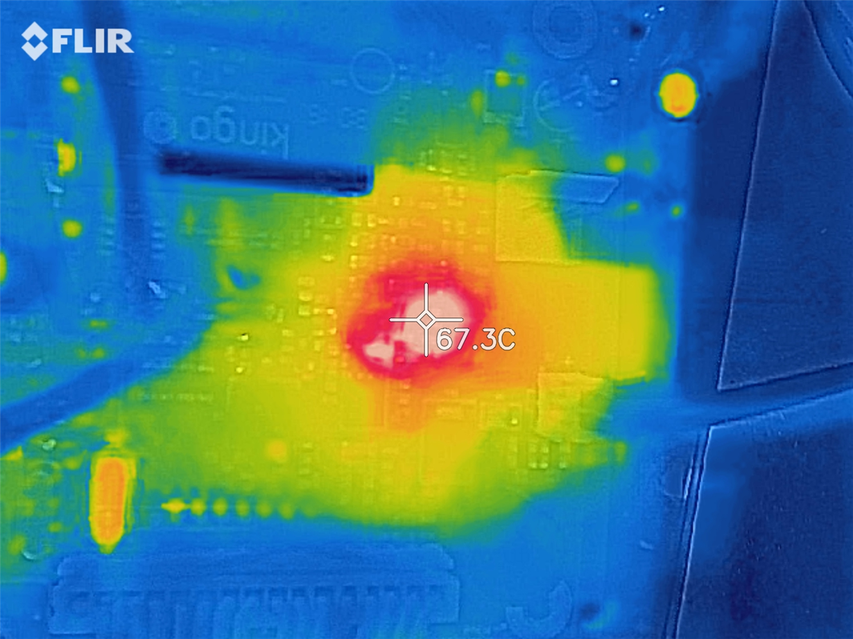
The following image is a thermal image of the burnt board. The measured current in the battery was 20mA and the current in the power supply was 890mA
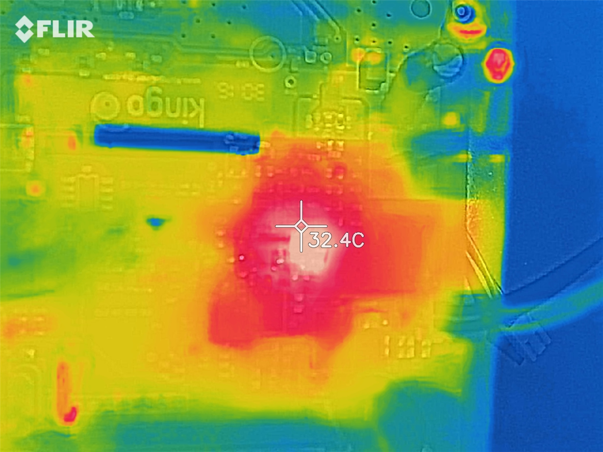
The IC reached a maximum temperature of 82 degrees Celsius, a thermal image of the same board but with a new IC is shown.
The measured current in the battery was 940mA and the current in the power supply was 890mA
We would appreciate your opinion on this matter and any suggestions to solve this issue would be greatly appreciated!


