Other Parts Discussed in Thread: LMZ14201
Tool/software: WEBENCH® Design Tools
Using WEBENCH POWER DESIGNER created a design using Part # LMZ14201H.
Dc input 12-13V , Output -5V , Output current 0.5A.
My question is Cout capactiance value. Is the simulation implying Qty 3, 22uf caps in parallel ?
Is the ESR of 3.71mOhm for one cap or all 3 in parallel ?
My concern is getting the correct about of ripple because this device requires some ripple for feedback.
Is there a formula for calculating the Required ripple ?
Below is the suggested values from simulation :
Cout22uF
3.71mOhm
Qty= 3
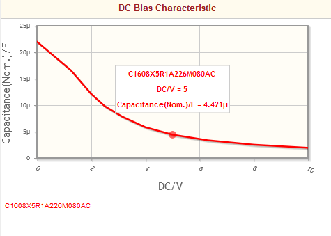
Cap = 22 µF
Total Derated Cap = 14 µF
VDC = 10 V
ESR = 3.71 mΩ
Package = 0603
One last question , what does Total Derated cap = 14uF imply ?
Thanks