This thread has been locked.

If you have a related question, please click the "Ask a related question" button in the top right corner. The newly created question will be automatically linked to this question.

TPS2H160-Q1: CS(H) voltage is only 2.27V in fault mode

Part Number: TPS2H160-Q1

Dear team,

My customer tested the TPS2H160-Q1 in their new project, but they found a problem. They set the current limit is 320mA. When they adjust the load current ups to 1A , the device is in over-current fault mode. The wave form is as below, from the picture we can see that the CS(H) is only 2.27V which is not in the normal range(4.5V-6.5V, VS=7V). 

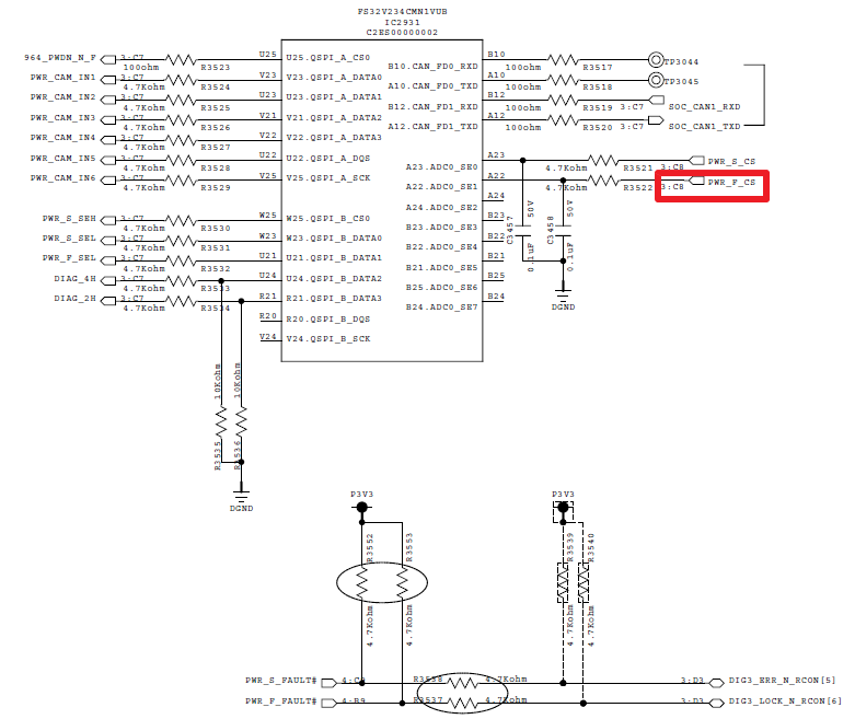
After checking, this error is caused by the SOC's pin AD_test which connected to the CS through a 4.7k ohm resistor. The AD_test pin can only sustain 1.8V max voltage, but when the fault occurs, CS(H) pin can up to 6.5V.  When the connection between the CS pin and the SOC's AD_test pin is disconnected, the fault voltage of the CS pin returns to normal range.

From the test we can see that we can't connect these two pins(CS pin and AD_test pin) through a resistor directly, then how do we connect them?  if this device can't work in this situation, could you please help recommend other device which can meet the requirement? 

Thanks & Best Regards,

Sherry

  • Hi Sherry,

    I have a questions about your setup. By my calculation, your customer has chosen a 1.5kOmh Current Sense resistor to get a linear range of 0V to 1.655V for a load current of 0A to 320mA. Is this correct?

    Then, during a overcurrent fault, the voltage is pulled higher than what the SOC can handle. Is the goal that the voltage during this fault be at 1.8V or be allowed to go up to 6.5V?By my understanding, the SOC needs this fault voltage to be clamped at 1.8V. Is this right?

  • Hi Shreyas,

    Yes, you are right.

    1. the linear range is 0V~1.655V, and the current limit is 320mA.

    2. The SOC needs this fault voltage to be clamped at 1.8V, so can this device achieve this?

    Thanks & Best Regards,

    Sherry

  • Hi Sherry,

    The device cannot end the linear range and report a high fault at the same voltage. There are two options for your customer but both come with some cons.

    The first is to decrease the sense resistance for 1.5kOhm to around 1.1kOhm. This will decrease your linear range to 0V->1.185V but should output a fault high value that is under or equal to 1.8V. This will take minimal change to the design but will reduce the resolution for the SOC.

    The second is to add a zener diode rated at 1.8V at the CS node. Note that zeners are not perfect and will have some variation, but this will keep the voltage clamped to 1.8V during fault high. The downside of this is that it may be difficult to differentiate between a full load current and a fault high.

    If the decrease in resolution is acceptable, I would recommend the first option as it just involves changing one resistor.

  • Hi Shreyas,

    Thanks for your reply!

    The CS(H) is related to the Rcs? In my understanding, CS(H) is not affected by changes in Rcs resistance. Could you please tell me what is the internal relationship between the CS(H) and Rcs?

    Thanks & Best Regards,

    Sherry

  • Hi Shreyas,

    Sorry, the fault description is a little wrong. When Rcs=1.5k, the test result is that voltage of A point VA=5.53V, voltage of B point VB=2.27V. When Rcs=1.1k, VA=5.53V, VB=2.46V. When Rcs=470 ohm, VA=5.27V, VB=2.54V. According to the test, CS(H) has no relationship with the Rcs, right?

    The AD_test pin's maximum volatge which is acceptable to customer is 1.8V, so we have to reduce the VA below 1.8V. One solution you have said before is adding a zener diode. Do you have any other solutions? 

    Thanks & Best Regards,

    Sherry

  • Hi Sherry,

    We are going to move this issue from E2E to a direct call and support.