This thread has been locked.

If you have a related question, please click the "Ask a related question" button in the top right corner. The newly created question will be automatically linked to this question.

TPS73633-EP: Overshoot during power up for 3.3V fix version

Part Number: TPS73633-EP

Hi TI Expert,

We are using TPS73633MDBVREP(fixed 3.3V) on one product design. 

There is an overshoot during power up. The schematic is as below.

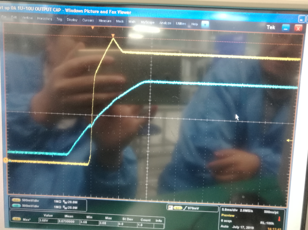
The overshoot waveform is as below, Iload=0A, Vout_Overshoot=3.68V. CH1(Yellow): Vout, CH2: Enable pin

(Photo is taken by a mobile phone, not quite clear.)


After changing R901 from 15K to 24K, the overshoot is disappeared. Waveform is as below. (This is to make Vout power up later)

Could you help to check and comment about the below two questions?

1. Why the overshoot disappear after changing R901 from 15K to 24K( the input voltage from ~2.4V to ~3.1V)?  Per the datasheet, the Vin input voltage range is 1.7V to 5.5V. Suppose the chip should work normal after the Vin is higher than 1.7V. If this is indeed related with the voltage level of Vin, what's the VIN threshold that we can enable TPS73633?

2. Per datasheet, the Enable high(Enabled) is 1.7V min. Per my understanding, this '1.7V' means ALL THE TPS73633MDBVREP can power up under TA=-55degC to 125degC as long as the Enable pin is 1.7V. The actual enable high voltage of different chips are all lower than 1.7V, right? Is there a typical value for this Enable High(Enabled)? 

http://www.ti.com/lit/ds/symlink/tps73633-ep.pdf

Thanks,

Dora

  • Hey Dora,

    There will be an issue with the device when the input voltage of the device is lower than the output voltage of the device.

    While the conditions are not the same as what is mentioned in the footnote, the following footnote is relevant in the fact Vin is not high enough to support running the device.

    As far as the enable pin threshold voltage, the datasheet is saying the range of input voltages for EN to turn the device goes to a min of 1.7 and max of Vin over temperature ect.

    The enable could obviously be lower and fit that description.

    Thanks,

    Daniel

  • Hi Daniel,

    Thanks for the feedback. It makes sense for your explanation for the first question.

    About the second question, I want to double confirm. If our setting of enable pin is 5*(1-5%)*15/(15+24)=1.83V, can this ensure ALL the chip be enabled? Just want to check if there will be potential issue during mass production. 

    Per our test in lab, the chip is actually enabled at around 1.1V to 1.2V. 

    Dora

  • Hey Dora,

    All chips will be enabled, but you could see overshoot issues due to the part I mentioned above.

    Thanks,

    Daniel

  • Hi Daniel,

    Do you mean we can't ensure the overshoot issue be resolved by changing R901 from 15K to 24K?

    According to our test result, when R901=24K, the overshoot is disappeared. 

    Do you have any suggestion how to fully resolve the overshoot issue if changing R901=24K is not the right solution? Our current schematic is as below.

    P5VSB_PSU is the output of the PSU. 

    Thanks,

    Dora

  • Hey Dora,

    If the overshoot goes away completely for your testing then it will be fine.

    Thanks,

    Daniel