This thread has been locked.

If you have a related question, please click the "Ask a related question" button in the top right corner. The newly created question will be automatically linked to this question.

TL5001A: TL5001A doesn't start when high current load is connected

Part Number: TL5001A
Other Parts Discussed in Thread: TL5001, LM5155

Hello,

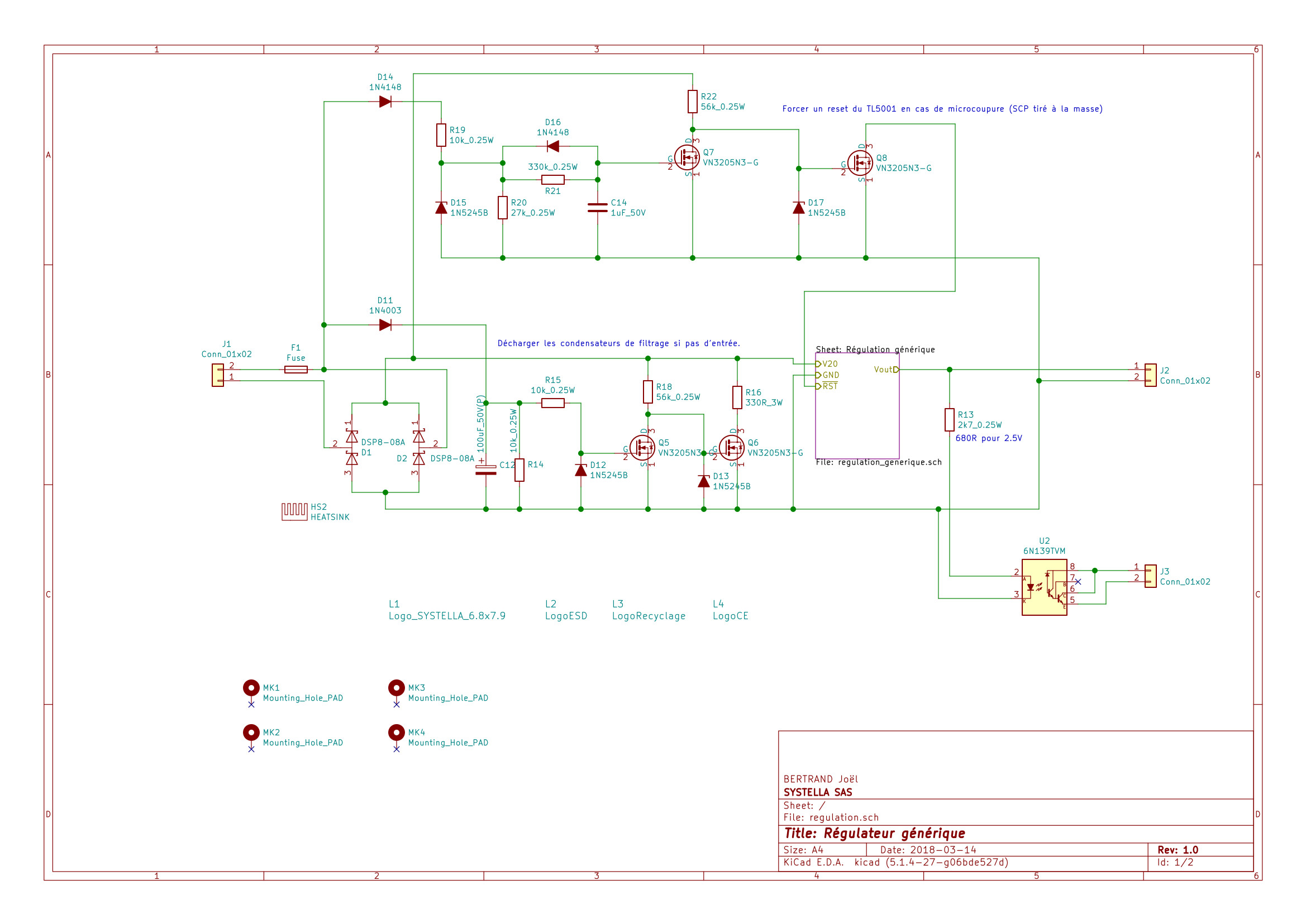
A long time ago, I have done a regulation with TL5001A. My circuit :

 Input comes from a 20Vac power supply and a rectifier. Thus V20 is about 28Vdc. C10 and C11 are discharged when main power is switched off (a 330R resistor is connected between V20 and ground when main AC power is lower than 3V for more than 1s). Thus, UVCO is reached after 3 or 4s without load. This discharge circuit is not on the schematic I have given.

Vout : 6.3V @ 10A (or 2.5V @10A with other feedback resistors).

When main power is switched on without any load, TL5001A will start as expected. With a 3A load also. But if I try to start this converter with, for example, an electronic load that consumes 5A, TL5001A doesn't start and Vscp raises to 2.4V. Converter detects a short circuit. If I pull SCP to ground, TL5001A starts as expected.

When TL5001A runs, I can raise output current until 15A without any trouble.

I have read "Circuit design calculations with TL5001" and I have tried to modify time constants (C2 and C3 in my case). If I modify C2 to 10µF, converter starts slower (I can show power on led) and stops with short circuit default. If I decrease C3 (I have tried until 12 nF), converter seems to start with greater load currents but with C3=47nF, efficiency falls (more than 3A/28V for 6.3V/4A !).

Second trouble. If main power supply is switched off and switch on again before UVCO condition is reached, TL5001A enters in protection mode also. I suppose these two issues are correlated but I haven't found solution.

I suppose I have done a mistake when I have computed R1, C3 and C2...

Help will be welcome.

Best regards,

JB

  • I have recomputed compensation network (method in "circuit design with the TL5001") and I obtain :

    f1 = 800 Hz

    f2 = 4500 Hz

    => C4 = 820pF, R4=1.8kR, C5=100nF, C7=18nF and R11=1.8kR

    I can replace these values, but is it possible that compensation network causes my issue ?

    Best regards,

    JB

  • Hi JB,

    Thank you for posting.  Can you put your e-load in constant-resistance mode instead of constant current mode?  The 5A e-load setting and a 3000uF output capacitor will take a large current to establish the output voltage, and it can easily trigger the SCP.  

    Loop may not be perfect but during startup before the output voltage established, the circuit operates in open loop and the modification of loop compensation should have little effects. 

    The TL5001 is an old part.  We have new devices like the LM5155 which you may consider for your design.  

    Best Regards,

    Youhao Xi, Applications Engineering

  • Hello,

    Maybe TL5001 is an old part, but this part is a DIP package and can run up to Vin=40V... I will try to reduce output capacitor.

    Best regards,

    JB

  • Some news.

    I have replaced output capacitor by a new one (330uF) without any result. My E-load is set to 1R (constant resistor).

    At this time, all tests will be done with this new capacitor. I will replace this capacitor with my 2200uF when all issues will be fixed.

    If I replace C2 by 10uF and C3 by 1uF, converter starts even @6A.

    But if I switch off power supply, I have to wait complete discharge of C10 and C11 capacitors to restart controller (4 or 5s). How can I restart this controller in case of very short power off/on cycle ?

    Best regards,

    JB

  • I have replaced output capacitor by 2200 uF and converter seems to run as expected with C2=10uF and C3=1uF. I will try to keep converter running during few hours.

    But power cycles issue is not fixed. Do you think I can put on SCP an external reset chip like Microchip MCP120 to force SCP to ground when main power supply is switched off ?

    Best regards,

    JB

  • Hi Joel,

    Thank you for the updating.  It sounds like a viable idea to control SCP externally. 

    Best Regards,

    Youhao

  • Hello,

    Problem solved.

    Bottom circuit discharges filter capacitors but is not enough to raise a UVCO condition after a quick power cycle. Top circuit is able to reset TL5001 (CSP is connected to Q8 drain). I have tried to use a MCP120 without success as TL5001 requires a longer reset signal (and MSP120 waits for a 5V power supply).

    Please update your application note and application design as :

    - Ccsp and Cdt values are 10 times lower than real values you have to use if you want to start controller without trouble on a real load (I tried to use values in application design and I'm unable to obtain a reliable result) ;

    - I think you have to indicate somewhere that, when main power is switched off, TL5001A tries to keep expected voltage on its output and raises an CSP condition ! I suppose this CSP condition is raised because duty cycle quickly changes. Thus, Ccsp is charged before C10 and C11 are totally discharged and it is impossible to restart TL5001A without a real reset circuit after a very quick power cycle or before waiting for UVCO condition that cannot occurs in a power cycle.

    Best regards,

    JB