Hello,
I am using the stock firmware (http://www.ti.com/tool/UCD3138FW-HSFB) for the UCD3138HSFBEVM-029 and attempting to understand exactly what is happening.
When the device is initially booted, Vout in the GUI is 0 V. Then, I switch on the device and the GUI reads ~128 V (0xFFFF). If I read the the actual PCB using a DMM, the voltages are what I would expect. For example, if I set
#define VOUT_0 (5120)
in pmbus_topology.h, then I will see 10V on the physical output. Additionally, I will see ~1V going into the ADC at node AD03 (per the datasheet which calls out the scaling as being ~0.101 Vout).
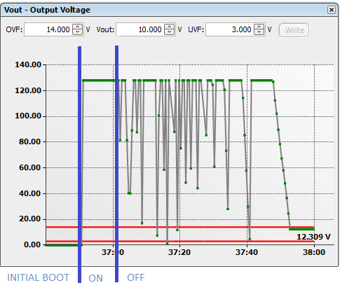
The above image has several areas to note. The first area is after the initial startup. Vout is at 0V. Next, S1 is switched on, enabling the output. After a short time, S1 is turned off, disabling the output. There are several areas of this that I don't understand. Why is Vout different before and after flipping the switch (0V vs 12.3V)? Why is Vout ~128V instead of 10V? Why does the output voltage swing so greatly after disabling the output?
I was looking through documentation for PMBus and noticed that there is a command for VOUT_SCALE_LOOP. It seems like this is just an ADC scaling issue, but I'm unable to edit this value. The PMBus spec says 29h would edit this value. Using the SMBus tool, I tried writing to 29h and it acknowledged the command, however nothing happens. Additionally, when checking the commands that show up in the GUI under the CMDS_DCDC_NONPAGED [MFR 21] parameter, 29h does not show up. So I'm unsure as to how I should be adjusting the scale. Again, my firmware and board are stock with no modifications other than Vout.
Software: Code Compose Studio Version: 6.2.0.00048 and Fusion Digital Power Studio 3.0.36
Thank you