This thread has been locked.

If you have a related question, please click the "Ask a related question" button in the top right corner. The newly created question will be automatically linked to this question.

TPS54531: Unable to disable the output using EN pin

Part Number: TPS54531

Hi, I implemented on a PCBA the typical application schematic found in the TPS54531 datasheet, as I need a power supply with equivalent specs. I am currently using it with a 14 V input. When the voltage on EN is higher than 1.25 V or when it is left floating, the device is having the expected behaviour and has a 5V output. When the EN voltage is below 1.25 V, 0 V in my case, I was expecting the output of the device to be off, but it is actually 5V. Even weirder, when a load is applied to the output, the voltage rapidly drops and when the load is removed the voltage goes back to 5V.

At the end of the day, what I am trying to do, is control the EN pin with a microcontroller to enable and disable the 5V supply. Is it theoretically possible? Do you see an issue?

Regards,

Leonard

  • Hi,

    Could you please share the schematic and waveform? Thanks.

    Shawn

  • Hi Shawn,

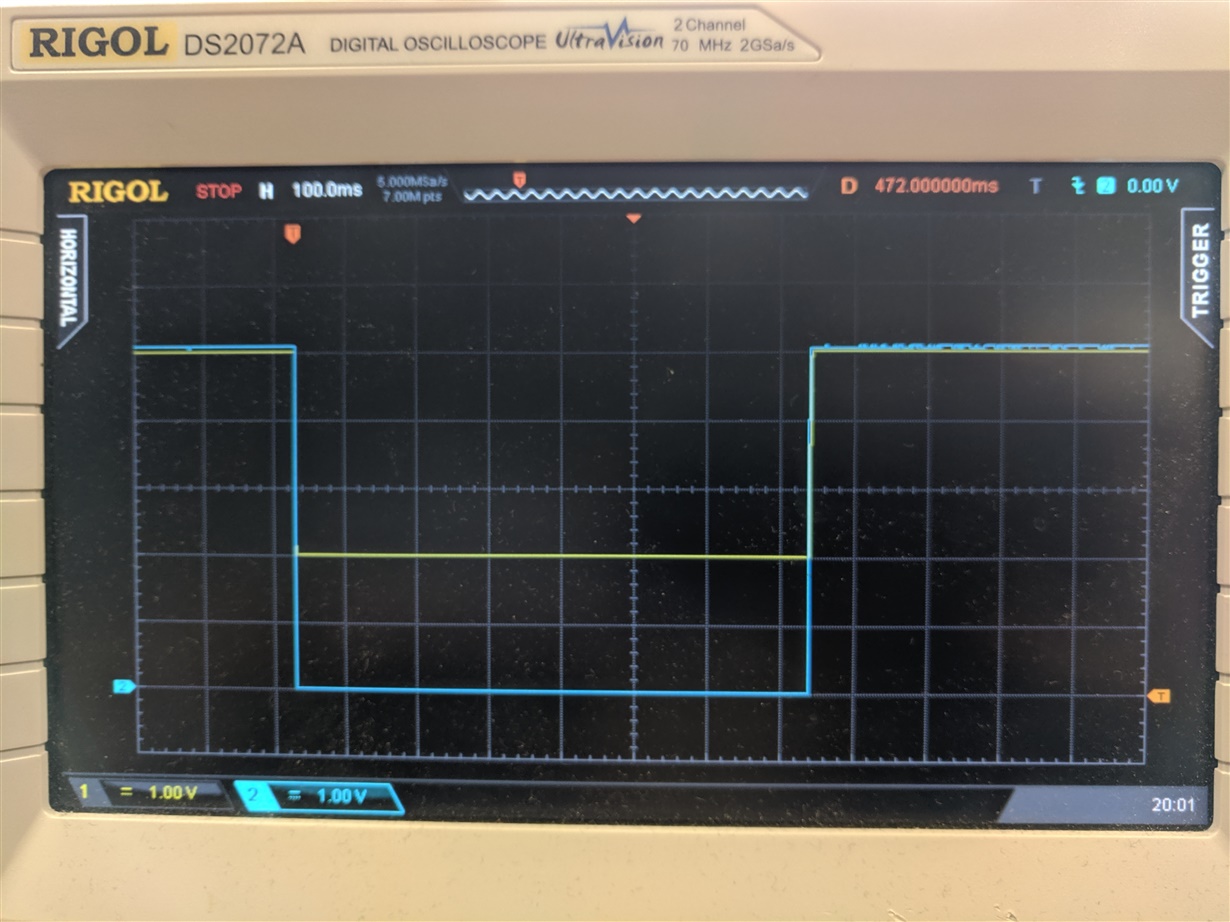
    Thanks for the reply. So here are the schematic and the waveforms (sorry for the quality, I was not able to take a screenshot directly onto my scope).

    Schematic : VPWR is currently 14 V

    Waveforms : In blue the voltage on the enable pin and in yellow the voltage outputed by the supply (5V).

    With a load : the EN pin is floating, and then I tie it to ground, the 5V become a 2V supply, and than goes back to 5V when the EN pin is floating again.

    If I tie the EN pin to ground, when there is no load the voltage is 5V and when I apply a load, the voltage goes down to 2V (as on the waveform above). Removing the load, cause the voltage to go back to 5V.

    The load is 5 ohms resistor.

    Regards,

    Leonard

  • Hi Leonard,

    The schematic looks fine, it is strange. Could you please share the layout? Let's review it to see any weakness.

    Shawn

  • Hi Shawn,

    Here are some pictures. Layout for top in orange, for bottom in blue and mid layer in green.

    Stackup :

    Top (orange)

    GND plane

    Mid layer (green)

    14 V plane

    GND plane

    Bottom (blue)

    Regards,

    Leonard

  • Hi Leonard,

    The layout is not bad, I don't think it will lead to this issue. The only concern is the R114 and R112 are a little far away from FB pin, but I think it is fine.

    Where are the 14V from? DC/DC power supply? Please check if there is current limit? And how did you tie EN to GND?

    Also, please test the waveform (VIN, SW, EN, VOUT, IOUT), let's see what happened in detail.

    Shawn

  • Hi Shawn,

    The answers to you questions:

    Where are the 14V from? DC/DC power supply?
    It comes from a lab power supply.

    Please check if there is current limit?
    There is no current limitation with the load.

    And how did you tie EN to GND?
    I shorted EN pin with the GND directly using a wire. (soldered to the pad)

    Here are the requested waveforms : https://www.dropbox.com/s/y7q6y8x2hlkxhqe/tps54531_waveforms.zip?dl=0. Again sorry for the picture quality. There is one set with the supply enabled (EN left floating) and one set disabled (EN shorted to GND). Every waveform was taken while a  5ohms load is attached directly to the 5V output. I did not measured the Iout waveform, but it should be identical to vout as the load is a fixed value.

    Regards,
    Leonard

  • Hi Leonard,

    I think this 5V comes from other circuit when the EN was connected to GND, what is the next stage circuit (load) for your application except for the load resistor?

    And if you connect EN to GND, and remove the 14V input voltage, what would happen?

    And did you check other board? Do they have the same issue?

    Shawn 

  • Hi Shawn,

    Yes you are right! The 5V (when the supply is disable) come from another source. It is another IC that I thougth needed 5V, but was actually only needing capacitors on its pins. Now that I removed the parasitic 5V, the circuit is working as expected.

    Thanks a lot for your help!

    Regards,
    Leonard