This thread has been locked.

If you have a related question, please click the "Ask a related question" button in the top right corner. The newly created question will be automatically linked to this question.

TPS55340: What will the Voltage Output be when the device is disabled?

Part Number: TPS55340
Other Parts Discussed in Thread: TPS22810, TPS61178

I have had a board produced and assembled with the TPS55340 circuit designed as was discussed in the related post.

My question is regarding the Enable of the device. 

Reference Figures 23 and 30 of the TPS55340 Datasheet (SLVSBD4C –MAY 2012–REVISED JANUARY 2015):

When the Enable is grounded so that the device is disabled, should the Voltage output be turned of as is shown in the figures?

My measurements of the built circuit:

Vin (Voltage Input) is 12.00VDC

Enable pin is 0.183VDC which is planned because the device is supposed to be off initially.

Vout (Voltage Out) is 11.86VDC with no load even though the Enable pin is Low.

When the Enable pin is high (approx. Vin) and Vout = 14.47VDC which is accurate for the selected Resistors.

When the Enable pin is returned low, Vout = 11.86VDC.

What other information can I provide to help determine if this circuit is working properly?

I really needed Vout to be turned off when the chip is disabled.  If this is not the way the circuit functions, the I'm very confused by Figures 23 and 30.

Thanks,

Steve

  • Hi Steve,

    Figure 23 is the start up waveform for a Boost topology converter. Schematic is shown in figure 16. For a non synchronous converter, when Enable pin is pulled logic low, the power supply Vin will charge output capacitor through inductor, high side rectifier diode to Vin minus voltage drop of diode. That's why you found Vout now is 11.86V. In figure 23, the Vin is 5V, before the EN pulled high, Vout is also around 5V. That's correct.

    Figure 30 is the start up waveform for a SEPIC topology converter. Schematic is shown in figure 25. When Enable pin is pulled logic low, Vin will charge both capacitor C6, D1 and output caps C8, C9, C10. Since the C6 capacitance is only 2.2uF and output caps capacitance is 66uF. C6 voltage is much higher than Output caps because of the same charging current and its much smaller capacitance. Therefore, the Vout before start up is almost 0V.

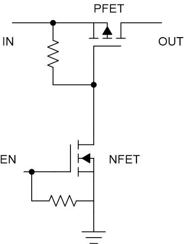
    If the 11.86V output voltage is not acceptable for you in shutdown mode, a load switch or a PFET in series at input is needed.

  • Hi Zack,

    Thank you for your detailed explanation.  I guess that I can use a reed relay, like a HE721C0500, to switch the power off.

    I guess it doesn't really matter whether I switch the input or the output but I believe that it will be easiest to switch the output for my application.

    If you see any issues with this idea, please let me know.

    Thanks again and have a good weekend.

    Steve

  • Hi Steve,

    It's good to use a relay at input or the output. There is no big difference.

    May I know the output power of your case? The reed relay you choose HE721C0500 can only support 5W. Please take care of it.

    TI has a lot of load switches products for you to choose: http://www.ti.com/power-management/power-switches/load-switches/products.html

  • Hi Zack,

    Your question is quite valid and appreciated. The maximum output power will be 15VDC @ .475A which exceeds the HE721C0500 capability but the HE721A0500 should handle it.

    I would prefer to use a smaller package but unfortunately, I can't afford to change the package type in the current design.

    For future designs, which device would you recommend to be used to switch the power off?

    Thanks!

    Steve

  • Hi Steve,

    Here is one load switch recommendation: http://www.ti.com/lit/ds/symlink/tps22810.pdf

    Besides that, you could also use discrete PFET solution as a load switch.

  • Hi Zack,

    Do the load switches like the tps22810 have short circuit protection?

    In my design, the TI power supply output voltage On/Off is controlled by the tps22810. 

    If the output is shorted to ground accidentally, does there need to be a fuse in line to prevent damage to either the load switch or power supply or will they be self-protecting?

    Again, thanks for all of your help!

    Steve

  • Hi Steve,

    TPS22810 doesn't have short circuit protection feature.

    Is your case input voltage 12V and output voltage 14V? What's the maximum output current? TPS61178 is a boost converter with load disconnect control and hiccup short protection feature, may be suitable for your case: http://www.ti.com/lit/ds/symlink/tps61178.pdf

  • Hi Zack,

    For my case

    Vin = 12VDC

    Vout = 12 to 18 VDC

    Iout Max = 800mA; Typ = 475mA

    Of course, if the output is accidentally shorted to ground, the potential current is whatever can be sourced which is what I need to protect. :)

    Thanks for your support!

    Steve

  • Hi Zack,

    Unfortunately the PCB design prohibits changing the regulator chip but I will keep it in mind for the next project.

    Could you recommend another load switch which can handle up to about 22V with a maximum current draw of 800mA?

    The TPS22810 only handles up to 18V.

    Thanks,

    Steve

  • Hi Steve,

    Sorry, I only supports Boost converter products, not familiar with load switch products. You can post a new thread on E2E and the the load switch expert will answer you.