This thread has been locked.

If you have a related question, please click the "Ask a related question" button in the top right corner. The newly created question will be automatically linked to this question.

TPS548B22: TPS548B22 circuit

Part Number: TPS548B22
Other Parts Discussed in Thread: TPS548A20

Hello Admin,

I have a question regarding the TPS548B22 need your help to address. Thanks.

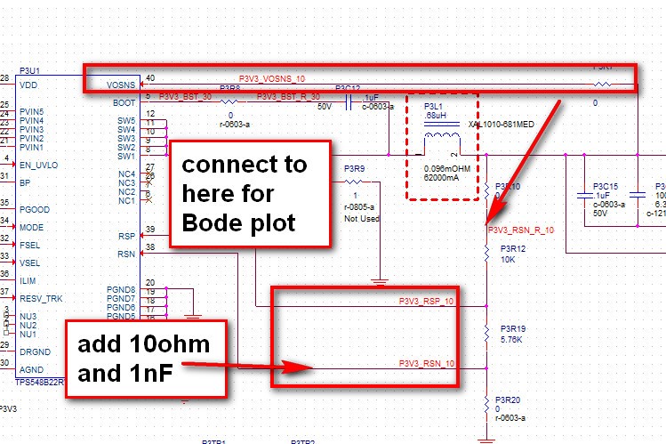
1. the existing connection of RSP, RSP follow EVM, but it is different with the Webench's circuit. Could you pls let me know which one is better? 

2. Should i change the VOSNS connect to FB connection for bode plot? pls refer the picture. thanks. 

regards,

YC

  • Hi YC,

      I would prefer to add 10 ohm in series with RSP and RSN pins and a 1nF in parallel to these pins - the could help filter out any noise if there was in the circuit.

    I dont see issues with your circuit shown above. Can you please be specific about what your question on the bode plot  is?

    regards,

    Gerold

  • Hi Gerold,

    thanks for your reply. 

    1. As this part have the differential remote sense, can i put P3R10 far away from the controller to compensate the pcb power plane's drop? If this is the case, why the RSP and RSN connect to the bottom side of the FB resistor? not the P3R10?

    2. If i will use the P3R10 to measure the bode plot,  the P3R10 is far away from the controller, and the P3R7 is connect to the the local Cout. Then the bode plot would be not the full part of bode plot? So i would move the P3R7 to connect to the Top side of the FB resistor. pls let me know your suggestion. thanks.

    regards,

    YC 

  • P3R7 is the 0ohm on the Top and right side. 

    P3R10 is the one connect to the Top side FB resistor. 

  • Hi,

       The P3R10 is the resistor which is used for bode plot measurements - where you would inject the signal. 

    As the P3R10 is part of the voltage sensing path, the top side connection of the P3R10 resistor should be close to the remote load. The resistor can be close to the IC - but the trace should be connected to the remote end.

    The P3R7 is not used for bode plot measurement.  VOSNS  is  used to monitor the output voltage to be used by the internal circuit inside the IC.

    Regards,

    Gerold

  • Hi Gerold,

    the P3R7 is for local voltage sense, if i move the trace of P3R10 to connect to the remote load and use the P3R10 to do the bode plot measurement. The injection from AP300 start from P3R10, flow through the TPS548B22's system, then back to P3R10. In that case the voltage sense of P3R7 will not in this system, so the bode plot will not correct. 

    The reason why i ask this question is when we measure the bode plot of the TPS548A20, local FAE suggest we move the P3R7's connection inside the injection loop to make sure the bode plot is correct. 

    Could you pls let me know which one is more accuracy for P3R7's connection? Thanks.

    Regards,

    YC

  • Hi YC,

    For bode plot check, recommend to disconnect P3R7 and connect VOSENS to the net between P3R10 and P3R12 as you draw. And change P3R10 to a value between 20~70 ohm, generally 51ohm is recommended, noise injection from P3R10. This will make the noise injection to both VOSENS and FB loop.

    Yuchang

  • Hi Yuchang,

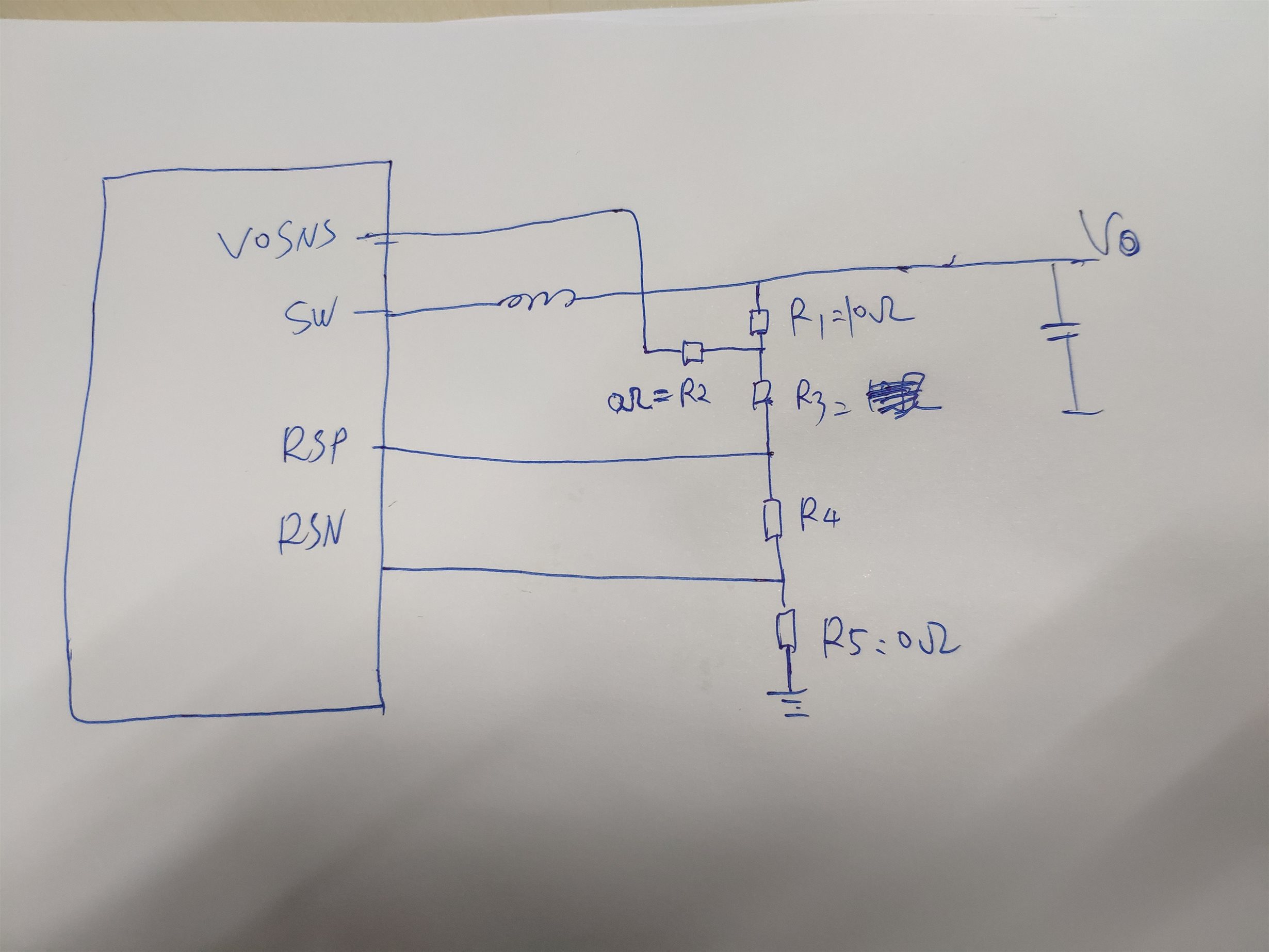
    Thanks for your feedback. Could you pls help check whether the connection is correct or not. Thanks.

    1. As i want to measure the bode plot, it can inject noise from R1. 

    2. On placement: I put R1, R2 and R5 to the load side and, routing as differential trace back to controller to compensate the voltage drop.

  • Hi YC, Correct and just recommend the injection resistor around 51 ohm.

    Yuchang