This thread has been locked.

If you have a related question, please click the "Ask a related question" button in the top right corner. The newly created question will be automatically linked to this question.

BQ25713: Loop compensation RC network calculation

Part Number: BQ25713

I found BQ25713 SW unstable issue in my charger design.

The PCB layout and components‘ value were refer to TI's EVB.

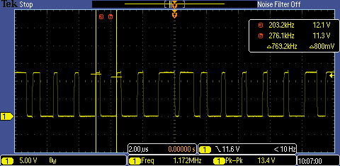
When Vin=5V, Vbat=12V, device works at Boost mode, SW2 waveform was shown below, the system was unstable:

SW1 at Buck mode shows same situation. 

In my design, Cvbus=80uF, Csys=120uF, Cbat=22uF, all capacitors are ceramic. But there's some polymer caps using in TI's EVB.

May the SW unstable issue was caused by ceramic capacitors?Is the RC compensation network suitable for all ceramic caps design?

  • Hi there,

         The VSYS POSCAP is crucial for stability, at least 7*10uF+47uF POSCAP are needed at VSYS node to guarantee stability. We don't recommend to change compensation network for ceramic capacitors only, there is potential stability risks for other operation modes.

         Another potential reason is load condition, how much load do you apply when this issue appear? Is there any possibility that over current condition is triggered?

    Regards


  • Hi there,

    We haven’t heard back from you. We are assuming you were able to resolve your issue. If not, just post a reply below or create a new thread if the thread has locked due to time-out.

    Regards,

  • Hi Shishuo, 

    I found the way to solve this issue. Add a polymer cap. between VBUS and ground can improve the loop stability.

    Thanks for your answer.