This thread has been locked.

If you have a related question, please click the "Ask a related question" button in the top right corner. The newly created question will be automatically linked to this question.

UCC28051: 3kHz ripple in AC line current

Part Number: UCC28051
Other Parts Discussed in Thread: UCC28050, UCC38050

I am trying to use the UCC28051 as a replacement PFC  control IC in a product that was originally developed for the now obsolete On Semiconductor  MC34262 PFC control IC.

The basic functionality seems Okay but I am getting some ripple current superimposed on the fundamental AC line current.

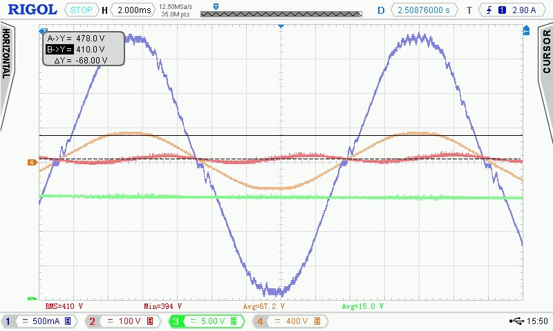
The ripple frequency is approximately 3kHz. See the oscilloscope capture below.

CH1 = AC line current,   CH2 = DC output voltage,  CH3 = Vcc for the UCC28051,  CH4=AC line voltage

Note: this measurement was taken with the PFC operating at approximately 350Watts output and the AC supply was connected via a Variac and Isolation transformer.

So the actual amount of 3kHz ripple current shown below is less than it would be when connected directly to the AC mains.

This 3kHz ripple current did not exist with operating with the On Semi  MC34262

My initial impression was that this was some type of instability resulting from incorrectly matched filters for the Pin2 and Pin3 inputs to the UCC28051 however I have spent several days working on numerous different combinations and nothing seems to reduce the 3kHz ripple current.

The only thing that I have found so far that reduces the 3kHz ripple current is drastically reducing the peak voltage at Pin3 (multiplier).

If I reduce the Pin3 input voltage low enough so that the Pin2 output voltage approaches the saturation limit then the 3kHz ripple will decrease, this approach reduces the ripple by about 50% however this drastic a reduction in multipler voltage creates other issue so by itself is not a viable solution.

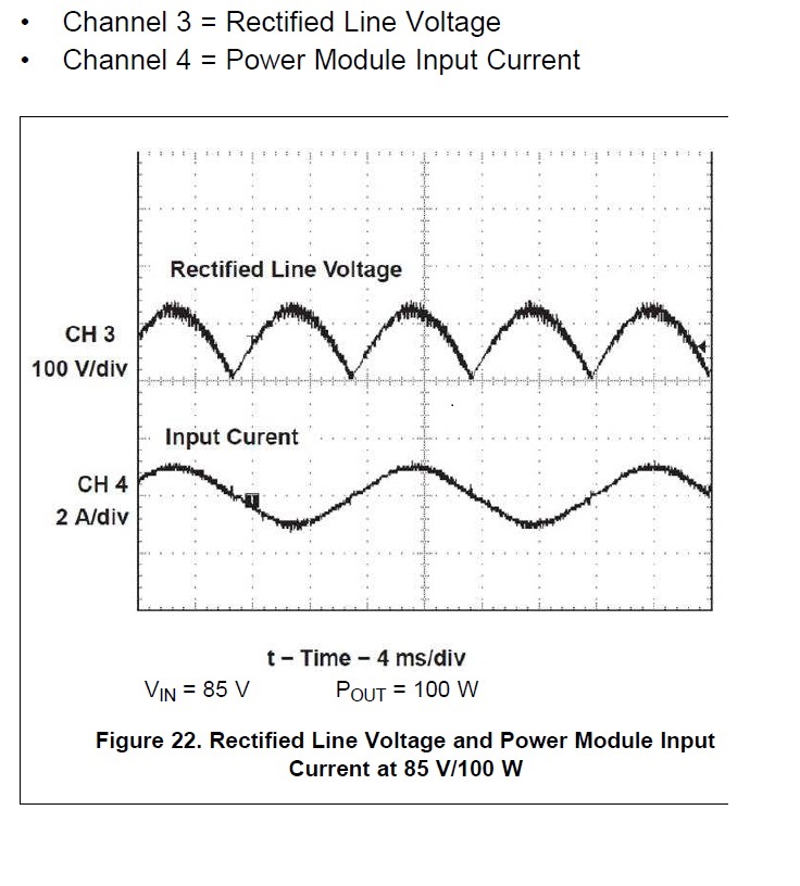
Is it normal for the UCC28051 to have this type of  kilohertz range ripple current?  It is difficult to tell based on the resolution of the oscilloscope pictures in the datasheet ( below)

If not do you have any suggestions regarding how to reduce/eliminate it?

Best Regards,

Jeff Ferrick

  • Hello Jeff,

    Could you study the inductor current just to make sure it is operating in critical conduction?  If you have too much output ripple voltage and output is not high enough it could cause the ZCD detection misfire. If the inductor current is going continues conduction most likely this is the issue. To resolve this just requires increasing the output voltage and/or capacitance if this is the case. 

    The other thing that adds to distortion is if the voltage loop crosses over at too high of a switching frequency and the loop is trying to correct for 120 Hz ripple.  The following application note discusses how to compensate the voltage loop of the UCC28050/1 devices if this is what is causing your issue.

    Regards,

  • Mike,

    I investigated the inductor current as you recommended and it is Okay, it goes all the way to zero on every switching cycle.

    Regarding your comment about output ripple voltage, can you please explain how the output ripple current can cause the ZCD circuit to misfire?  I cannot find any mention of concept in either the datasheet or app note.

    I have been reviewing the app note you recommended however that has been difficult because there are numerous inconsistencies between information in the app note and the component datasheet.

    1) both the datasheet and the app note reference the exact same 100W universal  input design however not all of the component values are the same.  specifically R3 and R7 do not match.  R3 is 30.1K in the app note and 15K in the datasheet.  It  is not possible to determine how the app note derived the R3 value of  30.1K because the app note equation contains an undefined constant "k".  R7 in the app note schematic is 0.4pohms (calculated value = 0.373 based on EQ#18 and R7 in the datasheet is 0.2ohms ( calculated value = 0.183 ohms based on EQ#3)  It seems highly likely that the datasheet is incorrect because an R7 value of 0.2 ohms results in a peak current limit value of 9.3Amps which is well in excess of the inductor's 3.1Amp rating.

    2) the equations for calculation of the C3 value are also different app note EQ#14 yields a minimum value of 60uF  and Datasheet EQ#10 yields a minimum value of 138.5uF.

    3) voltage loop compensation:  Datasheet  EQ#16 seems to be incorrect because using this Eq. the calculated value for C11 is 1290uF clearly an impossible value.  Subsequently EQ#18 uses the value of C11 to calculate the value of C9 so that is also an issue.  App note EQ# 26 yields a value of 1.38uF for C9 which is fairly close to the 1.0uF value listed on the schematic however EQ#29 yields a value of 2863nF for C11 which is more than double the 120nF value listed on the schematic.

    Other TI PFC control ICs I have used in the past have datasheets and app notes that contain not only the equations but also show the solved equations as they pertain to the reference design so that you can be certain of how to use them properly.  The datasheet and app note for the UCC28051 seem to create a lot of confusion to say the least. 

    In consideration of the errors and discrepancies described above can you please the correct equations are for calculating the values of R3, R7, C9, C11?

    Best Regards,

    Jeff Ferrick.

  • In reply to Mike O':

    Mike,

    I investigated the inductor current as you recommended and it is Okay, it goes all the way to zero on every switching cycle.

    Regarding your comment about output ripple voltage, can you please explain how the output ripple current can cause the ZCD circuit to misfire?  I cannot find any mention of concept in either the datasheet or app note.

    I have been reviewing the app note you recommended however that has been difficult because there are numerous inconsistencies between information in the app note and the component datasheet.

    1) both the datasheet and the app note reference the exact same 100W universal  input design however not all of the component values are the same.  specifically R3 and R7 do not match.  R3 is 30.1K in the app note and 15K in the datasheet.  It  is not possible to determine how the app note derived the R3 value of  30.1K because the app note equation contains an undefined constant "k".  R7 in the app note schematic is 0.4pohms (calculated value = 0.373 based on EQ#18 and R7 in the datasheet is 0.2ohms ( calculated value = 0.183 ohms based on EQ#3)  It seems highly likely that the datasheet is incorrect because an R7 value of 0.2 ohms results in a peak current limit value of 9.3Amps which is well in excess of the inductor's 3.1Amp rating.

    2) the equations for calculation of the C3 value are also different app note EQ#14 yields a minimum value of 60uF  and Datasheet EQ#10 yields a minimum value of 138.5uF.

    3) voltage loop compensation:  Datasheet  EQ#16 seems to be incorrect because using this Eq. the calculated value for C11 is 1290uF clearly an impossible value.  Subsequently EQ#18 uses the value of C11 to calculate the value of C9 so that is also an issue.  App note EQ# 26 yields a value of 1.38uF for C9 which is fairly close to the 1.0uF value listed on the schematic however EQ#29 yields a value of 2863nF for C11 which is more than double the 120nF value listed on the schematic.

    Other TI PFC control ICs I have used in the past have datasheets and app notes that contain not only the equations but also show the solved equations as they pertain to the reference design so that you can be certain of how to use them properly.  The datasheet and app note for the UCC28051 seem to create a lot of confusion to say the least. 

    In consideration of the errors and discrepancies described above can you please the correct equations are for calculating the values of R3, R7, C9, C11?

    Best Regards,

    Jeff Ferrick.

  • Hello Jeff,

    I want to dig into the problem before evaluating discrepancies in the data sheet and application note. Note the application note was used to design the UCC28050 EVM.  I am not sure why their are discrepancies between the data sheet and application.  I will take a look at this when I have a chance.

    First,  if you design the output capacitor based one + line cycle of holdup time their should not be a ZCD misfire.  The ZCD will be triggered if the input voltage becomes greater than the output.  Np/Nzcd when this occurs will change polarity triggering a ZCD when it should not.  This would cause the inductor  current  to go continues instead of CrM.  You have confirmed that this is not the case.

    The input capacitor to the PFC stage should pass the AC portion of the input current (120Hz) and the high frequency portion of  boost inductor current.   Neither of these currents is 3 kHz.  So where is that current coming from.

    1. Is your output stable?  It should have only 2XLinefrequency ripple
    2. I would suggest looking at your input voltage, input current, inductor current and output voltage to make sure their are no instabilities.

    Regards,

  • Hello Mike,

     1)  Yes, the output voltage stability is good, virtually no change from 185Vac to 250Vac and there is no sign of the 3khz ripple in the output.

    I do not see any sign of the 3khz ripple in the AC supply voltage other than a very small amount that seems to be the result of the interaction of the ripple current with the EMC filter inductor.  I have also tried operating the circuit directly from the AC mains without a variac or isolation transformer. I expected the magnitude of the ripple to increase however that was not the case.  When operated directly from the AC mains the magnitude of the ripple current remained essentially the same but the frequency shifted from 3khz to 5khz.  Also, as a sanity check to make sure that with all of the component   variations I have been trying did not damage or alter something I re-installed the original (but obsolete)  On Semiconductor PFC IC and have re-confirmed that the 3khz ripple does not occur with the On Semi part.

    Upon reviewing the history of this thread I see that there is one other item I have not previously mentioned.  When I first powered up this circuit with the UCC28051 installed the circuit was wildly unstable.  I found that the issue was pin 1 noise sensitivity, I added 2700pF from Pin1 to Pin 6 and the instability completely disappeared.  I found that any capacitance between 470pF and 4700pF seems to work just fine in terms of circuit stability and I did try changing the value of this pin1 capacitor to confirm that it has no impact on the 3khz ripple current.

    Best Regards,

    Jeff Ferrick

  • Hello,

    The UCC38050 uses a transconductance amplifier  and so does the on semi as far as I can tell.

    If you add a capacitor from Vo_sns to ground it will add a pole to the voltage loop.  The roll off of your voltage loop may be too high.  Also the on Semi device may have a different transconductance gain.  I was thinking that possible their might be a loop stability issue.  The following will get you to application note that describes how to compensate the voltage loop. 

    The UCC28051 does have a slew rate comparator to speed up transient response.  I don't think the on semi device has that.  If the Vsense pin is greater than 2.68 V the comp pin will sink 1mA into the comp pin to recover from a boost voltage over shoot.  If the vsense pin is less than 2.2V the comp pin will source and extra 400 uA to recover from an under shoot on the  boost voltage.  If their is too much 120 Hz on the VO_SNS pin it could cause this misbehavior.

    I would check the VO_SNS pin to see if their is excessive ripple voltage.  I would recommend keeping the ripple at the VO_SNS pin to less than 100 mV.  This is most likely what is causing your issue.  It can be fixed by increasing the boost capacitance and/or filtering at the VO_SNS pin.

    Regards,

  • Mike,

    I have previously tried increasing the size of the output capacitance as you have suggested above, I have tested values up to 3X the original value and it had no effect on the 3khz ac line ripple current.

    Regarding the UCC38050 app note, as detailed in my post on 1-22-2020,  I have tried many different  combinations based upon calculations from the app note as well as the datasheet and I get virtually identical results regardless of the voltage loop compensation.  Also Note as I previously described on 1-22-20, utilizing the equations from the app note and datasheet is somewhat  problematic because of the errors and discrepancies that currently exist.

    I appreciate all of your efforts to assist me with this issue but at this time it looks we have reached an impasse and I will need to make a decision regarding accepting the performance of the UCC28051 as is for this particular circuit application or look for a different PFC control IC.

    Best Regards,

    Jeff Ferrick.

  • Hello Jeff,

    Sorry about the issues you are having with the application note not exactly matching the EVM.  I do know that the EVM does not have the 3 kHz of high frequency ripple you are seeing at the input.  Also, I have not heard complaints that the application note has error in it.

    Could you send me your latest schematic to review?

    I would also like to see scope plots of the following.

    1. Boost Output Voltage

    2. COMP

    3. VO_SNS

    4. CS

    Also could you check if your plots on the input capacitor to make sure their is not an aliasing issue.  What you should see hear is the high frequency inductor ripple current * the input capacitors ESR.  This should track the inductor current.

    Regards,

    Mike

  • Mike,

    I have decided not to use the UCC28051 in this particular product line.

    Given enough time I am confident that we would have been able to define the specific cause of and solution for the 3khz ripple current issue.

    However the need for a production ready solution became urgent and it was simply not practical to pursue this option any further.

    Once again, thank you for all of you assistance.

    Best Regards,

    Jeff Ferrick