This thread has been locked.

If you have a related question, please click the "Ask a related question" button in the top right corner. The newly created question will be automatically linked to this question.

UCC256404: feedback current, which corresponds to "no deviation"

Part Number: UCC256404
Other Parts Discussed in Thread: TL432, TL431, TINA-TI, UCC25600

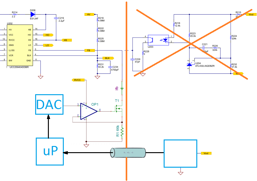
I'm thinking about using the UCC256404 in my current design.
Because of mechanical restrictions I can't implement a
direct feedback from secondary side using an optocoupler
and TL432. I've an indirect signal, which is higher than
3,3V on positive deviation and lower than 3,3V on negative
deviation of the secondary side voltage.

With images circuit I want to translate the feedback
voltage to a current feeded into UCC256404s FB pin by
connecting drain of T1 with UCC256404s pin 5.


Because I can't find a feedback current I_FB, which
corresponds to "no deviation" (I've assumed 50uA
in my simulation), I suppose, I've a wrong idea, how
the UCC256404 works.

Is there a feedback current, which corresponds to "no deviation"?

  •  A typical way to simulate the optocoupler is to use two bipolar transistors like the shown:

  • It seems I have expressed myself misleadingly.
    Question wasn't, how to replace the optocoupler in the simulation -
    instead I want to know, how to inform the UCC256404 to increment
    or decrement power transfer, when I haven't access to the secondary
    side power rails, but information via a fast side channel,
    if secondary output voltage is good, too high or too low (0, +1, -1)?
    I want to close the control loop with a microcontroller and
    the circuit, posted before.

  • Your DAC has a analog output behaves like TL431, your OP1 is a voltage follower - you need change T1 to the circuit I showed. But if T1 has a good linear range to follow OP1 - then it is ok. I like you change T1 to two transistors I provided since the two transistors can simulate the optocoupler much in a similar way. But I am not sure how good T1 (MOSFET) can do. But you can try T1 to see it works and if not come back to use the two transistors. 

  • OP1 isn't a voltage follower in my design - together with T1 and R1 the circuit builds a precision voltage to current converter.

    I've tried to reproduce the AC behavior of TL431 / optocoupler .- by asking for the feedback current I_FB, which corresponds to

    no deviation, I wanted to fix the DC operating point of my circuit (in my simulation I've used 50uA for that), because my knoledge

    of the DC behavior of TL431 / optocoupler combination is to small to reconstruct its DC operating point - I can't determine,

    which feedback current flows, when there is no deviation of Vout!?

  • I think you need to change T1 to the circuit of two transistors circuit I provided and have a try. I suspect your T1 not having enough linear work range. So OP1 would need quite large gate change in order to make its Vgs change.

  • There is no problem with Vgs, when using a 2N7002.

    Changing the T1 to PNP/NPN, will no change the circuit (besides the voltage current converter will be less precise because of NPN's base current) - the simulation shows that.

    Both circuits have a DC operating point of 50uA (3.3V / 66k).

    I've tried to find out the DC operating point of the TL431 / optocoupler combination by simulation using the optocoupler from "slum425.tsc" TINA-TI Reference Design (with Current Amplification = 100), but something seems to go wrong. I get a DC opertaing point of 0uA, but because Ifb can't become negative, the result should be wrong. I don't know, what's going wrong!?

  • Which simulation software are you using ? There is no Tina-TI model for this device - where did you get the model ?

  • As I wrote - I've copied the optocoupler from "slum425.tsc" TINA-TI Reference Design for the UCC25600 and changed the "Current Amplification" to 100.

  • Which simulation software are you using for UCC256404?

  • I use Ti TINA, but until now, none of my simulations include the UCC256404.

  • I use Ti TINA, but until now I haven't used the UCC256404 in my simulations.

  • UCC256404 does not have a TINA-TI model so your effort seems leads nowhere in terms of UCC256404. I suggest you not to continue such an effort. If you want to use a different device which has a TINA-TI model, you can start a new E2E thread but use a relevant title.

    I am closing this thread.

  • Original question was - which feedback current I_FB corresponds to "no deviation"?

    Or how to set the operating point of I_FB?

    Simulation stuff was a result to clarify this question.

  • Please use a different thread title for your support need. The thread title is not related to your question. Or simply remove UCC256404 from your thread title. Your thread title can cause misleading.

    I am closing this thread. Please open a new thread with a proper thread title.

  • ??? Why does the thread title not related to my question, when I ask, how much current I've to sink from UCC256404's FB pin to indicate, output voltage has no deviation ???

  • UCC256404 does not have a TINA-TI model so we cannot support you on UCC256404 based on TINA-TI. If you want to study UCC256404, you have to use an existing available model.

    If you want to get support TINA-TI, you can find a device with TINA-TI model. But you cannot use UCC256404 to get TINA-TI support since this device does not have TINA-TI model - these will confuse other E2E users who may assume UCC256404 has a TINA-TI model - there will be a lot of effort to clarify if this becomes a reality.

    So please ask a support to a device in an available environment.

    As you are using UCC25600 to understand your circuit, why not you ask your questions with UCC25600?

  • I do not use the UCC25600 to understand my circuit, I've only copy the optocoupler used in the simulation of the UCC25600 Reference Design to have one (I haven't found an optocoupler in the standard TI TINA library.

    It seems, the operating point of I_FB is load dependent, as first measurents with an EVM-020 show.

    I suppose, the operating point of I_FB will move to the 82uA for small loads or no load

    while it falls to 50uA and beneath for middle and higher loads.

    CH1: gate voltage low side driver

    CH2: I_FB measured with a 10k resistor

    CH3: voltage at resonaz capacitor

    Therefore I tend to use theTL431/optocoupler combination in my design, although I don't need the isolation it offers.