This thread has been locked.

If you have a related question, please click the "Ask a related question" button in the top right corner. The newly created question will be automatically linked to this question.

LM5176: Constant Current Loop ans SS pin for input/output Power Limiting

Part Number: LM5176
Other Parts Discussed in Thread: INA213, LMV431A

Dear *,

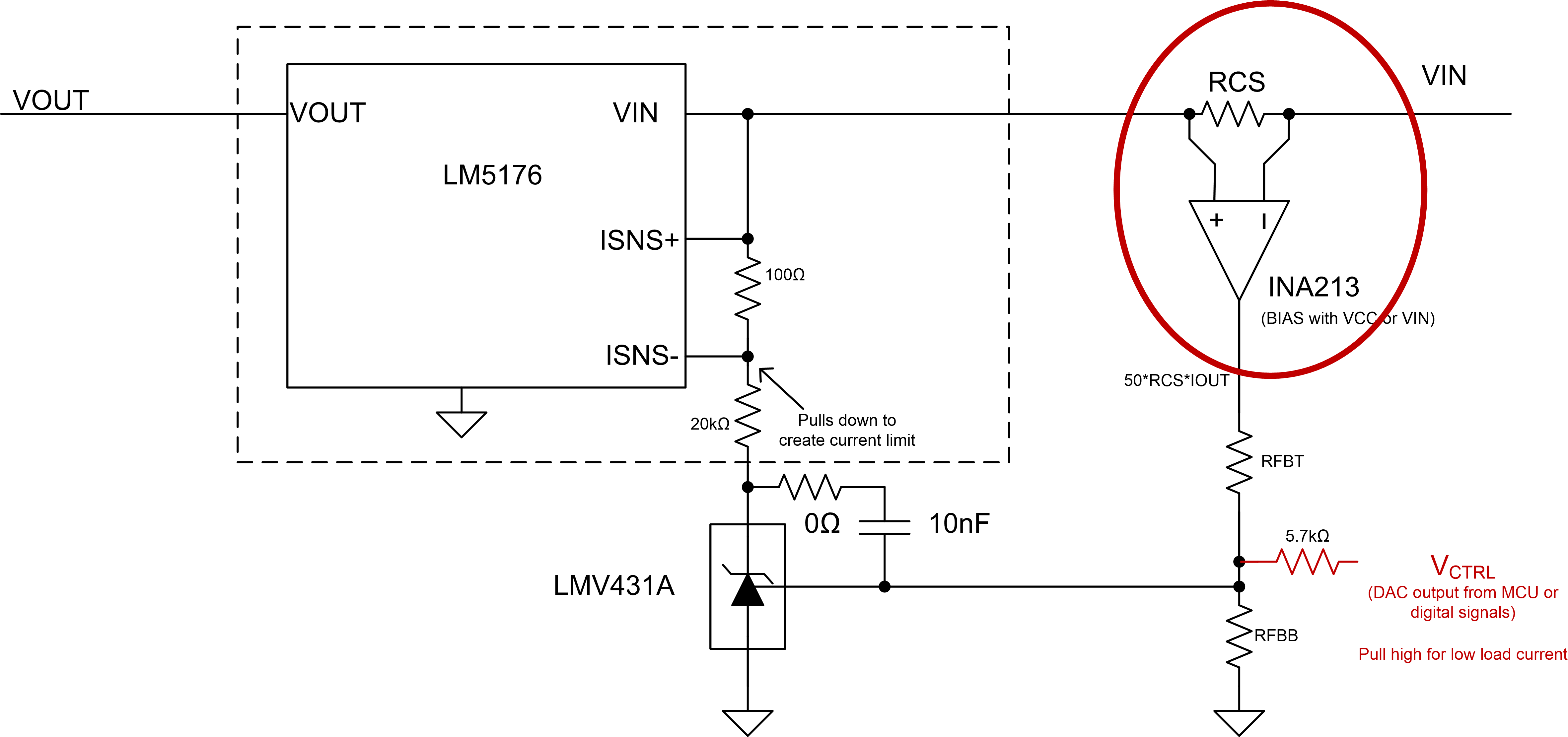
we are designing a Buck-Boost supply with LM5176 and want to limit input power to 25W. We will use ISNS at the input current.

Our input voltages in normal operation are from 12V to 24V, while UVLO=9V and Vhys=1V, for vin high we allow +3V

So the Vin range is from 9V to 27V. In-order to limit the input power to 25W, and if the  RSNS is constant , then we have for different input voltages/currents different voltage drops across Rsns that will satisfy 25W.

Eg for 12V max input current is 2A and for 24V is 1A and so on. If we size the Rsns for lower voltages ( eg 12V 2A) then this will not work for 24V.

Is it possible to control the SS pin with a DAC in conjunction with ISNS input current in-order to limit input power to the LM5176?

Or is there a better way to limit input power of the LM5176?

Best Regards,

David.

  • Hi d_zero

    Thanks for reaching out with your questions and using the LM5176 in your design.

    It is not recommended to pull the SS pin down with an external supply .However the ISNS pin can be used to limit the input current. See the schematic below.

    Please let me know if you have any questions.

    Thanks,

    Garrett

  • Hi Garrett,

    is it possible that you explain how the proposed circuit is working?

    1) The INA213 has 50V/V gain -> output voltage from Vo_INA is 50* Rcs * the input current through the series resistance.

    1a) what is the best selection for Rcs? are there any limitation except power dissipation and voltage drop?

    2) the LMV431A is a shunt regulator  we adjust the Vo_SR( chatode pin voltage) = based on RFBT RFBB, 5.7k and Vo_INA ?  

    2a) how to calculate Vo_SR?

    2b) how to choose RFBT and RFBB?

    2c) why is the series DAC resistor 5.7k?

    2d) What is the purpose of 0r and 10nF?

    2e) is there a reason for 20k res value and 100Ohm res value?

    Best Regards,
    David.

  • David,

    The basic idea is to sense the input current through the current sense amplifier (can be a different IC as needed). Assuming the output of the amplifier is 0V to 5V the feedback resistor are there to scale the voltage down to the the reference voltage. When the current sens signal voltage is higher than the reference voltage the voltage reference pulls down the ISNS- pin engaging the internsl average loop current loop and limiting the input current.

    The 20kOhm value just ensure that the Voltage reference doesn't exceed the rated voltage. the 100ohm just allows for a small voltage drop across the ISNS= and ISNS- pins. The 10nF is the feedback loop for the reference and ensures staable operation when the current limit is triggered.

    Let me know if you have any questions.

    Thanks,

    Garrett