This thread has been locked.

If you have a related question, please click the "Ask a related question" button in the top right corner. The newly created question will be automatically linked to this question.

TPS51220: Voltage Drop/Rail Collapse

Part Number: TPS51220
Other Parts Discussed in Thread: BQ25713

Hello,

I am currently using the TPS51220 as a DCDC on my system, generating 12V and 5V from a 19.5V source. I am seeing issues once I start drawing current from the TPS51220. Below are three images to help explain my issue.

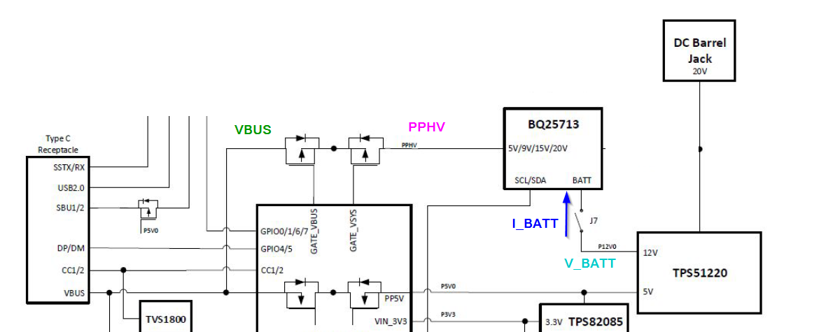
  1. Block diagram of the power path architecture for my system, highlighting connections for oscilloscope measurements
  2. Oscilloscope capture where V_BATT was supplied by the TPS51220
  3. Oscilloscope capture where V_BATT was supplied by an external bench supply
  4. Schematic for the TPS51220 on my design

As shown in the block diagram, the TPS51220 12V output is connected to the BATT pin of the BQ25713, simulating 3 cell battery. The problem occurs when the output of the BQ25713 transitions from 5V to 20V. There is a large amount of in rush current with consecutive current spikes follwoing, until the PPHV/VBUS rail eventually collapse. I am trying to determine what could be causing the PPHV/VBUS lines to collapse and if my implementation of the TPS51220 is at fault. When I use an external bench supply to replace the 12V supply from the TPS51220, the system works perfectly fine.

I also have a few questions that if you could answer would be helpful 

  1. Why is there such a large voltage drop from the TPS51220 that never seems to recover? Shouldn't the feedback circuit of the TPS51220 kick in?
  2. What would cause the consecutive current spikes? 

Using the TPS51220 to supply V_BATT

Using an external bench supply for V_BATT

  • Adam,

    I think maybe the consecutive current is caused by the 12Vout value change, so the first thing recommended to check is why there is around 2V drop at 12Vout when the big inrush coming.

    Did you test the transient/ripple performance with 12Vout without connected BQ25713? If not, please check first.

    Seems C32/C33 a little bigger, commonly around 100~200pf is proper

    What's inductor DCR and output caps ESR spec?

    Yuchang

  • Hello Yuchang,

    Thank you for your comments. 

    No, I have not checked the transient/ripple performance of the DCDC on its own. Will add this to my test list

    I'll change C32/C33 to 100pF. Believe that was an error on my part. It will take me some time to conduct this test due to the South campus closures. Will try to get to the lab this week though.

    The inductor DCR is 34.2m ohm (https://www.mouser.com/ProductDetail/Wurth-Elektronik/74437356047?qs=HXx4m3XcTe0HwqjLhQQgXw%3D%3D ) Also it seems this inductor is almost out of stock. Do you have any recommendations based on my requirements? (12V 6A)

    The capacitor ESR is 0.1 ohms

  • Adam,

    Maybe you check this one, but after change inductor, you need retune RC current sense net value to meet RC=L/DCR.

    http://www.cyntec.com/upfile/products/download/VCMT104T-MN5.pdf

    After you get test result, we can discuss more.

    Yuchang

  • Hi Yuchang, 
    After doing more testing, it seems the problem is that the 12V output cannot supply more than 1A without the output voltage decreasing dramatically. Attached is capture of the output of the 12V supply connected to nothing but a resistive load. You can see as I decrease the resistance to increase the current draw, the voltage drop follows. Any ideas as to why my 12V output is not stable and cannot handle more than an amp? I used an external bench supply as my system supply so there is plenty of curret/power being supply to the TPS51220

  • Hi Adam,

    From the waveform, My question is why the 12Vout is lower than 70% for long time but why 51220 not latch off because of UVP? Is the EN or Vin UVLO be triggered when the loading coming? Did you check EN and Vin waveforms?

    Yuchang

  • Hi Yuchang,

    Please disregard my previous scope capture. I believe there was a problem with my test setup. Here is scope capture that seems to make sense but need your help determining what could be causing this?

    As you can see, as I decrease the resistance connected to P12V0, increasing the current, it eventually shuts off at around 2A and remains shutoff until the load is completely removed where it then comes back to 12V. My circuit should be able to supply more than 2A so would you be able to double check my design?

  • Hi Adam,

    The point is still why 12Vout not enter latch off when it entering 0V (trigger UVP) due to the big loading. if UVP latch off triggered, only can be reset by toggling EN2/EN or Vin. So If Vin is stable, There should be En2 (not EN) triggered low then cause 12Vout reset, please check EN2 waveforms.

    And BTW, not recommend EN1/2 connected to Vref, because the SS end level need to over 2V.

    Suggest EN1/EN2 floating or connected with system signal or Vreg3.

    For your circuit if you can't disconnect EN1/2 and SKIPSEL, you can try to connect them to Vreg5 to try.

  • I conducted the same test procedure, but captured the voltage of VREF2 which is connected to EN2. It remains high during 12V OUT voltage drop

    Also, I believe that connecting EN1 and EN2 to VREF2 should be okay since the datasheet says that the voltage just needs to be above

    Any other ideas as to why the 12V outputs shuts off at 2A?

    Also, the 5V supply works perfectly fine and is able to supply 5A of current 

  • Adam, For Enable, the threshold is not a problem, but as I said, soft-start end need the EN over 2V, so don't suggest to tied it to vref2, I see your Email, let's discuss this question with Email continuously and close this thread now.

    Yuchang