Other Parts Discussed in Thread: TPS55340
Hello,
I designed a boost circuit using TPS61087 to boost the voltage of a Li-Ion cell up to 16V. The battery is monitored on the PCB by a uController which will turn off the DC/DC when the input voltage is lower than 2.9V.
The circuit is being used to drive a small brushed motor with speed regulation via PWM at aroung 31kHz.
The schematic is the following:

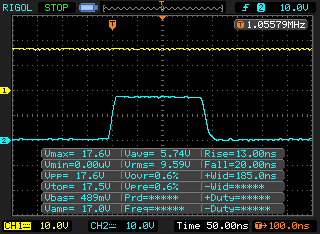
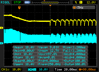
The output voltage is stable, with small ripple when the motor commutates the internal windings. The motor stall current is around 0.55A.
I monitored the output voltage between MOTOR+ and GND_DCDC during motor stall and there is no overshooting. The voltage drop over L202 during operation is negligible.
If the stall is longer than a few seconds the TPS61087 fails short between SW and GND. No other components fail. This was replicated several times with different results:
- "soft" short between SW and PGND (10-100 Ohms)
- "hard" short between SW and PGND (<1 Ohm)
- "active" short, meaning that the device measured outside the circuit measures no short but when it is inserted back in the circuitm the TPS61087 dissipates >1W even when turned off.
I would need some help to understand why the IC does not survive during high output power.
What is the current/voltage limiting mechanism when the output power is high?
What does the IC do when it's internal temperature rises to a value close to Tj_max?
What does the IC do if it detects it cannot regulate the output voltage to the proper level?
As the input power source, for the usual tests I use Li-Ion cells, but the defect also appears when using a lab bench power supply with remote sensing the voltage directly on the PCB.