This thread has been locked.

If you have a related question, please click the "Ask a related question" button in the top right corner. The newly created question will be automatically linked to this question.

LMZ31710: A power on start problem of lmz31710

Part Number: LMZ31710

Design requirements: VCC_ When 5V is not working, the lmz31710 does not output voltage. When VCC_ After the 5V voltage is started, the lmz31710 outputs 1v0 voltage. The lmz31710 has no en, and the INH pin is used to control the chip start.

Questions:

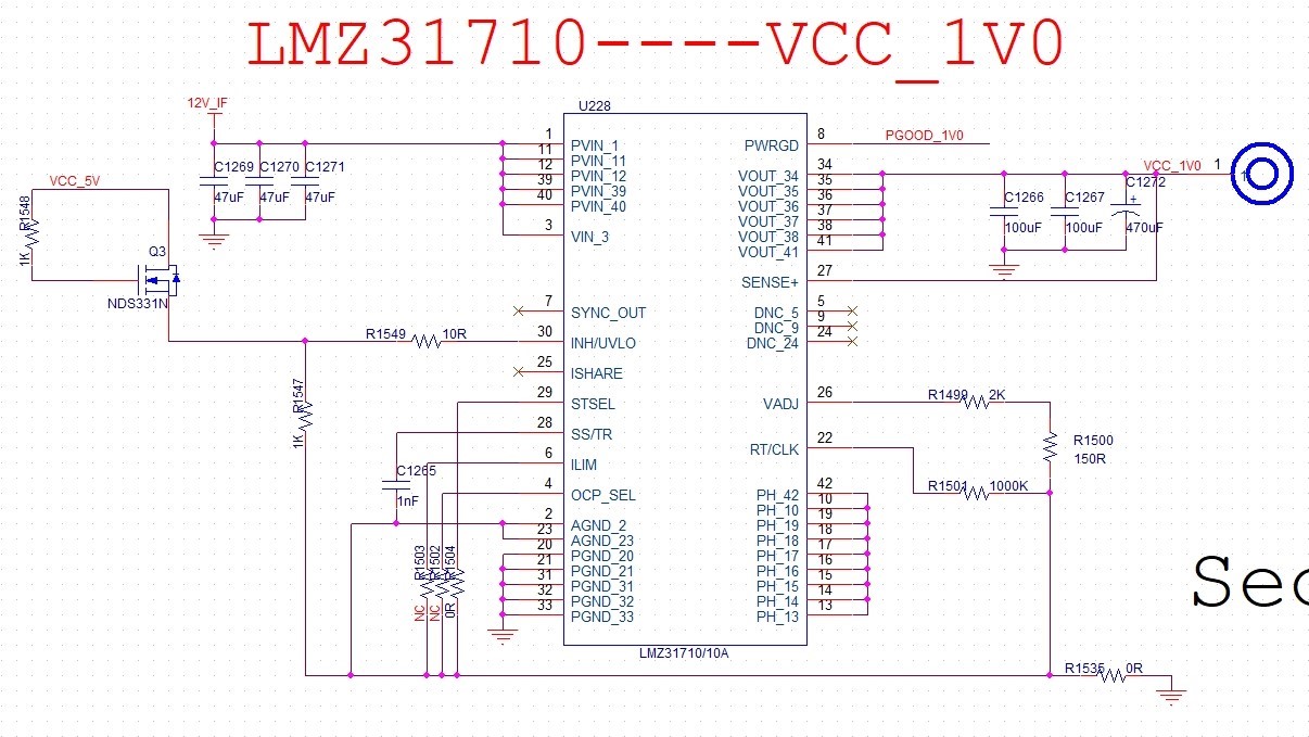
1. Can functional requirements be realized by MOS switch as follows?

2. It is mentioned in the manual that INH pin has built-in pull-up resistance, but the resistance value and pull-up level are not mentioned. How to determine the external pull-down resistance value?

3. Please help to see if the schematic design is reasonable?

  • Hi Zhang

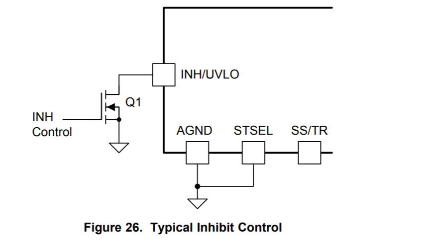
        As the device has an internal pull up, you need a MOSFET to turn off the device. The way you have connected the MOSFET in the schematic above is not needed. Please use the MOSFET in the way recommended in Figure 26 of the datasheet.

    Regards,

    Gerold

  • Hi Zhang,

    The INH pin has a pull-up current source of typical 1.15uA (see INH input current spec in Electrical Characteristics table) which is connected to an internally generated 3V. Once the LMZ31710 part is enabled, the pull-up current increases to a total of 4.45uA (1.15uA+3.3uA hysteresis current).

    If LMZ31710 should also be disabled when 5V rail goes down (12V still up), then the pull-down resistor should pull the INH pin voltage below the 1.1V INH low threshold considering the full 4.45uA pull-up current, i.e. the Rpull-down << 1.1V/4.45uA < 247kohm. The chosen value should be even lower than this value due to tolerances in the 4.45uA current, which is satisfied in your schematic with the very low value of 1kohm pull-down resistor.

    In Figure 26 that Gerold attached above, often Q1 FET is the open-drain Power Good FET of another regulator IC. If your 5V rail is being generated by another regulator with PGOOD, have you considered just directly connecting its PGOOD to LMZ31710 INH pin?

    Regarding your schematic, please keep AGND and PGND connections separate. As noted in the LMZ31710 datasheet, AGND and PGND are internally connected in the LMZ31710, so these nets should be kept separate in the application schematic/layout. You have a 0ohm resistor R1535 connecting AGND and PGND together that is unnecessary.

  •  

    As  points out, yes, your circuit above will work.

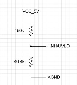
    The LMZ31710's INH/UVLO (Inhibit / Under Voltage Lock-Out) pin can be used to hold the part off if there is no 5V present, however, the circuit you have provided defeats the function of the UVLO circuitry by feeding it with a low-impedance pullup using the diode connected N-Channel MOSET.  Rather, I would recommend connecting a resistor divider directly from VCC_5V to the INH/UVLO pin.

    This way, you can size the resistor divider so that the LMZ31710 does not start-up until VCC_5V is at some target voltage, such as 4.5V.  The current circuit will start the LMZ31710 as soon as VCC_5V is a MOSFET gate threshold above 1.1V.  In addition, you can use larger resistors to reduce the current draw from the VCC_5V supply.

    The INH/UVLO pin is designed to provide a programmable UVLO with a programmable hysteresis through the external resistor divider selection.  The first step in sizing the resistors is to select the amount of hysteresis desired so size the top resistor, and then size the bottom resistor to select the turn-on threshold.  For my example I will use a 4.5V turn-on threshold and 4.0V turn-off threshold.

    We size the top resistor of the divider to have a voltage drop equal to the desired hysteresis voltage - the Turn on voltage minus the Turn off voltage (4.5V - 4.0V = 0.5V) with the hysteresis current (3.3uA).  Rtop = 0.5V / 3.3uA = 151kOhms.  Selecting a standard value, we get 150kOhm.

    We size the bottom resistor of the divider so that the voltage at the INH/UVLO pin is at its threshold (1.1V) when VCC_5V is at the turn-on voltage (4.5V) with Rtop and without the hysteresis current.  Vthres / [ (Vturn-on - Vthres) / Rtop - Iinh_off ] = 1.1V / [ (4.5V - 1.1V ) / 150k + 1.15uA] = 1.1V / [22.6uA + 1.15uA] = 46.19k-Ohms.  Select the closest standard resistor value of 46.4kOhms.

    In addition, as  points out, you'll want to make sure you separate AGND and PGND on the PCB, these are connected internally and connecting them externally can create ground loops that would introduce unwanted noise is sensitive analog circuits within the converter module.