This thread has been locked.

If you have a related question, please click the "Ask a related question" button in the top right corner. The newly created question will be automatically linked to this question.

LM2736: LM2736Y does not generate correct Vout issue

Part Number: LM2736
Hi TI experts:
There is a project followed TI LM2736 datasheet figure 22 to design 5Vin to 3.3Vout.
Max duty is 90%~94% which means min Vin =3.67V. When Vin > 3.67V, the converter should generate 3.3Vout.
 
 
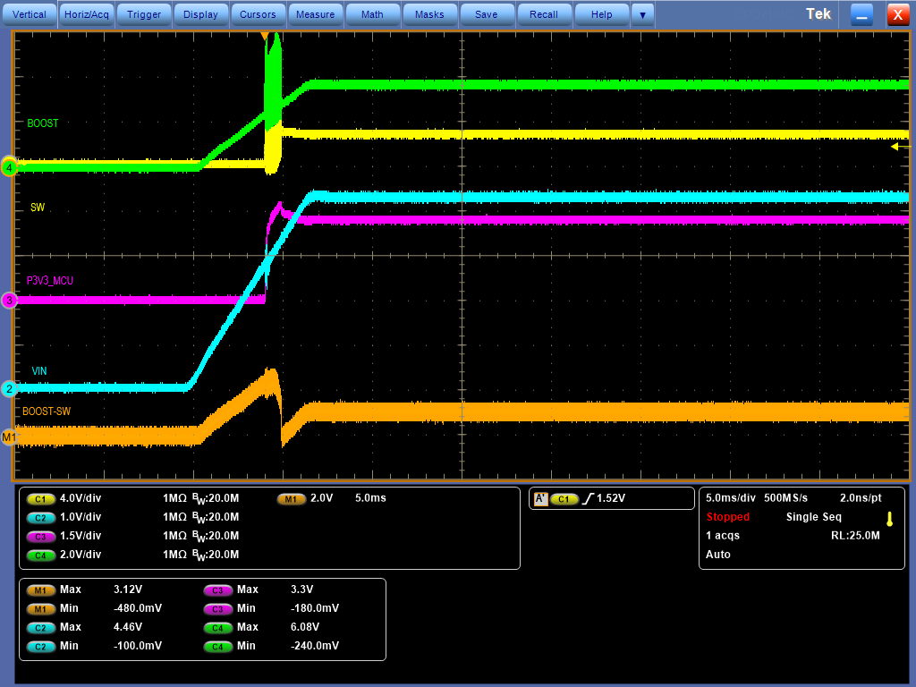
We can find when Vin < 4.8V, the converter will not switch and Vout is < 3.2V, not as 3.3V wanted.
 
However, when we draw a small current, like 10mA~50mA, then the converter start to switch.
In the waveform, current draw at around -4us, and the converter start to switch at around -2us.
 
What’s the criteria that LM2736Y (600kHz) start to switch?
Could please explain why it does not switch before -4us in the waveform? Is the MOSFET working in a linear region?
 
Thank you.
 
TI datasheet:
0 0 V IN V D TON t t Inductor Current D = T ON /T SW V SW OFF T SW IL IPK SW Voltage LM2736 SNVS316H–SEPTEMBER 2004–REVISED DECEMBER 2014 www.ti.com 7 Detailed Description 7.1 Overview The LM2736 device is a constant frequency PWM buck regulator IC that delivers a 750 mA load current.
www.ti.com

 
  • Post waveform and schematics. Seems contents in description field does not show the pictures properly.

  • Jeff,

    Can you post your actual schematic?  Does this only happen during start up?  Can you post a waveform including VIN, VOUT (no offset), BOOT and SW?  I would like to see both a longer time scale that shows the complete slow start sequence as well as another zoom in on the first actual switching pulse.

  • Thank you, John.

    Schematics is same as the datasheet fig 22. What the only difference is my Vin is designed as 5V but datasheet is 12Vin. 

    For margin test, I input Vin as 4.75V as input low margin and do the test.  When Vin =5V, things back to normal. The problem happens only during start up, and with Vin < 5V (like 4.8V).

    Yes, it is only happened during start up. After I draw the low output current (~10mA), then everything looks normal. Even I lower down input to like 3.6V, LM2736Y still can generate correct 3.3V wanted.

    Suspecting the IC stuck at some soft start. Have you ever met this before? Thank you again. 

  • Jeff,

    You are using exactly the same BOM?  I will still need to see the waveforms.  Questions on this converter come in very rarely, so we have not seen this particular issue before.

  • Hi John,

    Sorry to correct datasheet figure # that we followed, it is Figure 27. The difference including the inductor used is 2.2uH, additional compensation cap 5500pF in parallel with Voltage divider upper resistor 16.5kOhm and input cap C1 used is 1uF.

    w.r.t waveforms:

    I set up a Vin ramp up from 0V to 4.2V with 0.625V/ms slew rate for test again.


    From the waveform, we can find during Vin ramp up @ 3.359V, LM2736 is pulling down Vboost pin voltage to turn off H/S MOSFET switching.

    Question: Are we encountering some IC protection? What is the protection activated?


    After IC stop switching, we can find IC resume to switch and back to work if there is a small current exerted on the output side.

                Question: What’s the criteria to get rid of the stop switching (protection) condition and pull IC back to work?

     Why a Iout load can put everything back in track and work normally?


    Please refer to below 3 waveforms with remarks below.


    Waveform 1:

    When t = -10ms, we can find Boost-SW = 0V and it looks Vboost is pulled low by LM2736 itself because Vboost pin voltage is pulled low.


    Waveform 2:

    When t = 5ms, Vboost = 4.623V – Vsw = 2.986V = 1.636V, showing it is ok to drive High Side FET ON because 1.636V > MOSFET Vgs.

    But don’t know why LM2736 stop switching.


    Waveform 3:

    When t = 5ms, VIN = 3.359V while Vout is 3.3V, do we have possibility to induce MAX duty protection or UVLO protection or UVP protection?

    What’s the protection activated and how to recover from protection?


  • Jeff,

    We are looking into this.  Unfortunately we do not have any available hardware for testing at the moment, so it may be a while.  We will keep you posted.

  • Jeff we are still waiting for hardware.  The current situation (and you know what situation is affecting us all) is delaying deliveries.  We hope to have some information in the next 10 days.  Thanks for your patience.