This thread has been locked.

If you have a related question, please click the "Ask a related question" button in the top right corner. The newly created question will be automatically linked to this question.

LM338: Negative Voltage Regulator of 3A or greater

Part Number: LM338
Other Parts Discussed in Thread: LM337, LM317, LM237, LM137, UA79, LM79, LM120

I currently have a positive/negative power supply design using the LM317 for the positive side and the LM337 for the negative side but need more than the 1.5 A they can provide.  I see that the LM338 is a substitute for the LM317 that can handle in excess of 5A and should work perfectly. However, I can't find an equivalent for the LM337.  Is there such a chip or is there a better approach?

Thanks,

Mike Pitman

  • Hi Mike,

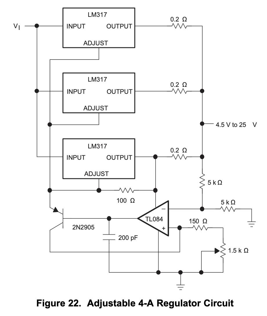
    We don't have a higher current negative LDO at the moment, but you should be able to leverage this application idea from the LM317 datasheet to parallel devices for more current:

    Do you think you can make this work?

  • John,

    It still seems to me that the LM338 or the above circuit will do the trick for the positive side.  Are you saying that there is no way to get a higher current output on the negative side?  Since there is no higher current negative LDO is there a way to convert the positive current from the LM338 or above circuit to negative?

    Thanks,

    Mike

  • Hi Mike,

    John is correct, there is not a negative LDO with 5A current limit.
    The LM137, LM337, LM120, LM237, UA79, LM79, LM320 and LM120 all provide 1.5A of current on a negative rail.

    You would need to float the positive LDO if you were to use it for a negative rail.
    Most designers choose not to go this route for this amount of current.

    John's technique above gives you all of the features in an LDO with the additional current.
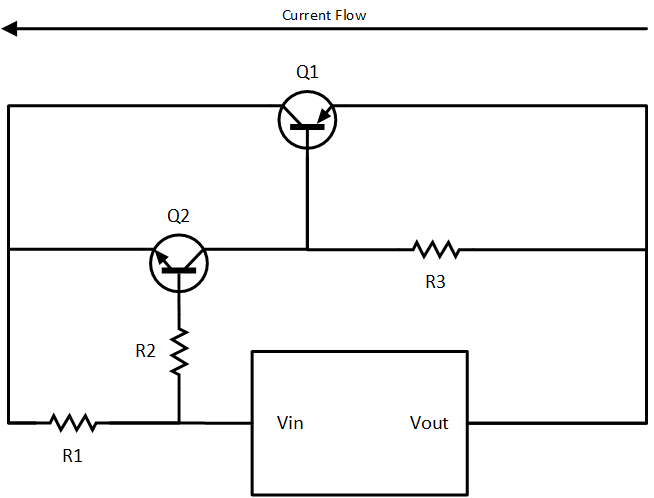
    If you want something simpler at the expense of some protection features at the higher current range, you can adapt the following circuit from the LM317 datasheet for a negative rail.  The 22 ohm resistor multiplied by the output current, sets the threshold where the darlington pair turns on, providing additional current to the output.  You will not have thermal protection of the BJT's or over current protection, but in many applications that is not needed.  If you do need those features then you will want to consider the approach John provided.

    Thanks,

    - Stephen

  • Hi John,
    This circuit does look doable for the positive side.  Do you think the same type of arrangement would work for the negative voltage?  The 317 datasheet shows this higher current supply design but the 337 datasheet does not.  Also, is the multiple 317 design better than a single LM338?
    Thanks,
    Mike
  • Hi Mike,

    This circuit could certainly be adapted for a negative rail.
    I'm pretty sure the main difference is changing the BJT's for their alternative counterpart.
    So an NPN becomes a PNP, and a PNP becomes an NPN.

    I've been studying these older application circuits in an effort to modernize them, and I have noticed that they still used the original part numbers from when they were designed in the 1970's or 1980's.  So if you choose to use these application circuits, you may wish to locate modern SMD equivalents, which will save you significant money and board space.

    Thanks,

    - Stephen

  • Hi Mike,


    Using Stephens recommendation or mine really depends on your comfort level, personally I think the multiple regulators are better as they share current and have inherent protection in the event of a load short. Also, they help spread the heat. For this reason, multiple LM317's might be better than a single LM338. The external transistor solution may need some more thought to ensure the circuit is robust. 


    I am not sure why a sharing application idea was not added to the LM337 datasheet, this came after the LM317

  • Hi John,

    All good reasons to go with multiple LM317's.

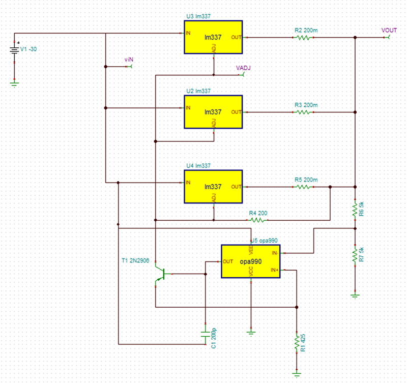
    Any ideas on  duplicating this method with the LM 337's?

    Mike

  • Hi Mike,

    On the surface, this configuration seems to work.  I would definitely recommend getting EVM's of both devices to see if the control scheme works in practice. 

    I think more time fine-tuning is definitely in order to ensure this works properly in the application. 

  • Hi Mike,

    If you don't mind can you send me a note with the application requiring 3A or more on the negative rail?

    We are looking at making a next-gen higher current negative LDO. 

    Thanks

  • John,

    I have a dual voltage (positive and negative) variable power supply using the LM317 and LM337 that works great as long as the load is less than 1A as the internal DC/DC converter is rated at 1A.  When a stepper motor was attached the voltage would be pulled down.  It turned out that the motor required over 2A to operate.  So the decision was made to develop the same power supply with a 3A DC/DC converter.

    Based on all the information you have so graciously provided, it's probably time to close this issue.  I will do some testing with the solutions given and if need be reopen the case.

    Thanks for all of your help.

    Mike