This thread has been locked.

If you have a related question, please click the "Ask a related question" button in the top right corner. The newly created question will be automatically linked to this question.

LM2621EVAL: Altium design files for LM2621EVM

Part Number: LM2621EVAL
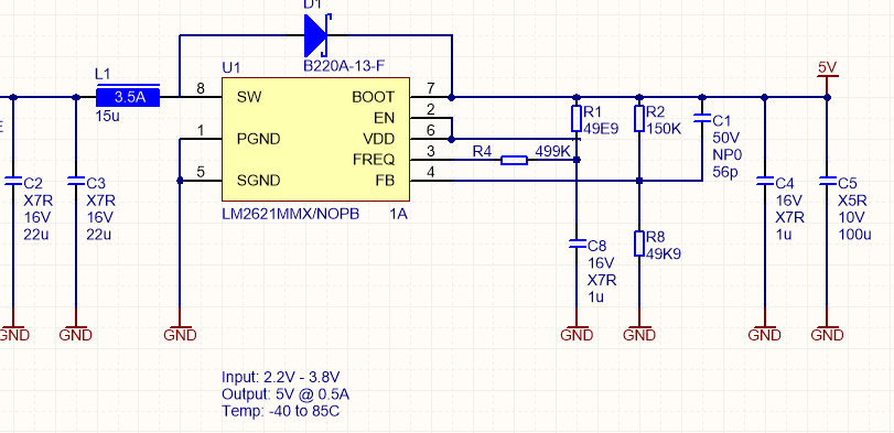
Other Parts Discussed in Thread: LM2621, TPS61022Team we are working on a design from some time. We used EVAL board during proof of concept. Later we used Webench values in design. The newly fabricated hardware is working correctly as per webench design but when we increase output load the output Voltage dips. This is not happening with EVAL board. Please request you to share the Altium files of eval board so that we can identify the gaps.
  • Hi Mayank,

    Thanks for choosing TI boost converter.

    I tried to find this part's Altium files but didn't find it because this is a really old part. All I have is the below recommended layout.

    Could you share your schematic and layout so that I can take a look at it? Thanks.

  • Hi Zack,

    Thanks for prompt reply!

    If you can share the BoM (specially Inductor) and frequency of operation that will be great.

    I am attaching schematic PCB Images. Initially it was designed for 0.5A but now we are looking for in excess of 0.7A. Inductor has been changed to 6.8uH / 3.5A

    2 Layer PCB, 1oz copper. No ground on other layer.

  • Hi Mayank,

    Sorry I don't have the BOM neither. 

    I will check it with EVM on bench. Please be patient.

  • Hi Mayank,

    I didn't have the LM2621 EVM on hand so I order a new one from ti.com last week. Normally it takes one week for shipment before I receive it.

    In the meantime, I would like to ask you is it possible to change to a new TPS61XX boost converter. TI has a lot of new RTMed devices can meet your requirement.

  • Hi Zack,

    Thanks for the arranging the same.

    I have noticed that LM2621 may not be sufficient for our load - we are powering up GPRS modem with that. It worked well during prototyping for some reason, but with actual hardware we are getting intermittent issues - may be due to peak power demand from GPRS Modem. Average current demand is around 200-300mA and we tested (constant load) circuit till 700mA. We have buffered the modem power supply with 20 x 100uf Ceramic caps, place very close to modem power pins to reduce glitches in power supply. But it doesn't seem to be sufficient. The peak power demand of GPRS modem may change in remote areas where signal strength is not sufficient.

    I think we will try with the new TPS61XX boosters.

  • Hi Mayank,

    To confirm with you, the input voltage range is 2.2V~3.8V, output voltage is 5V and peak load current is 700mA. May I know the peak current on time?

    I'll search for a suitable TPS61XX boost for you later.

  • Hi Zack,

    System powered by LiSOCL2 battery. Input Voltage 2V - 3.8V, Output 5V.

    Self Consumption: 1.5maH per day

    MCU load: 30mA

    GPRS Average Current: 400mA

    GPRS Peak Current: 2A (during transmission)

    I hope this information is helpful.

  • Hi Mayank,

    For your application, since the maximum output power is 2A*5V=10W, the inductor average current is 10W/2.0V/0.9= 5.55A. TPS61022 is a suitable deivce for your application.

    Please take a look at the TPS61022 datasheet.