This thread has been locked.

If you have a related question, please click the "Ask a related question" button in the top right corner. The newly created question will be automatically linked to this question.

TPS62173: IC fails and outputs ~0.6V or ~1.3V

Part Number: TPS62173
Other Parts Discussed in Thread: TINA-TI,

Hi,

I have built a bunch of boards with this regulator for a 5V output. Most of them work okay. Some failed, outputting either ~0.6V or ~1.3V.

Vin = 9V to 13V, En = 5V, L=2.2uH, Cin = 10uF, Cout = 22uF + 4.7uF

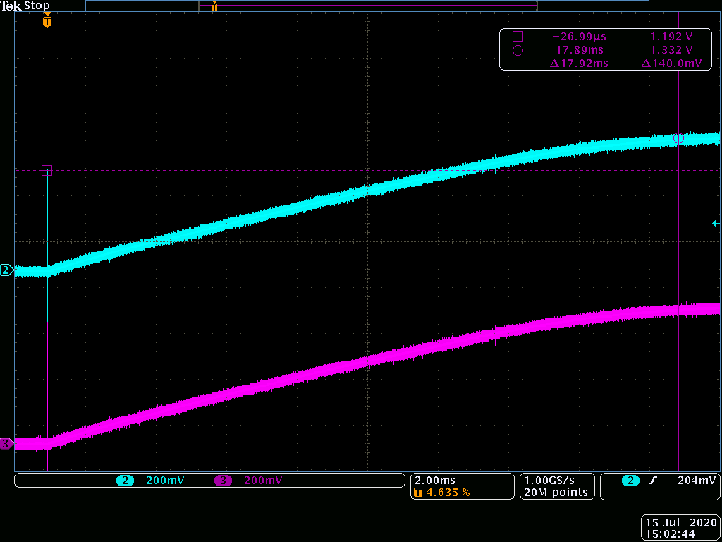
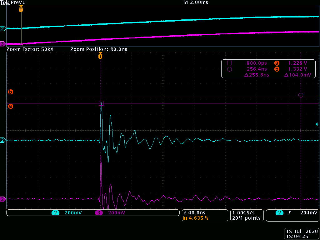
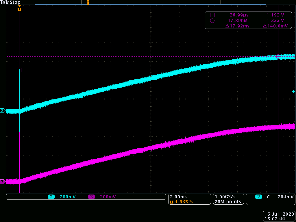
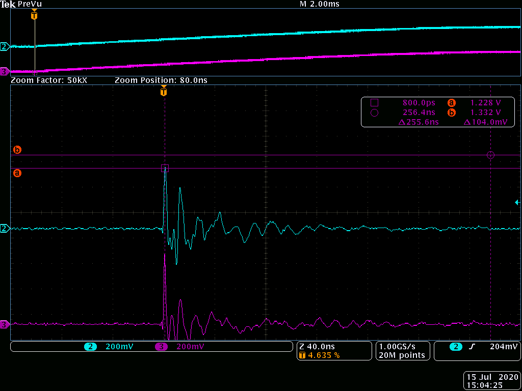
I took a scope shot of a bad regulator, and it seems to have a short spike once enable pin is turned on, but goes back to 0V, and gradually rises(like an RC charging waveform) to 1.3V. One channel is on the IC switch output, the other channel is after the inductor, on the node where it should have been 5V. I checked the inductor with an LCR meter and it is indeed 2.2uH. What could have caused the IC to be damaged?

Thanks,

Enyu

  • Also, the output load is only about ~20mA.

  • Enyu,

    Does this issue always happen at startup or the IC works for sometime and then you see this 0.6V or 1.3V output? Is there a way you can share the switch node waveform for the good and bad case both for comparison. Also, can you share how much output current requirement during startup and steady state?

    Regards,

    Amod 

  • Hi Amod,

    This always happens at startup, tho some of these boards have worked before. Steady state current is about ~20mA. Inrush current would be equivalent to charging up ~30 uF of caps on the output rail.

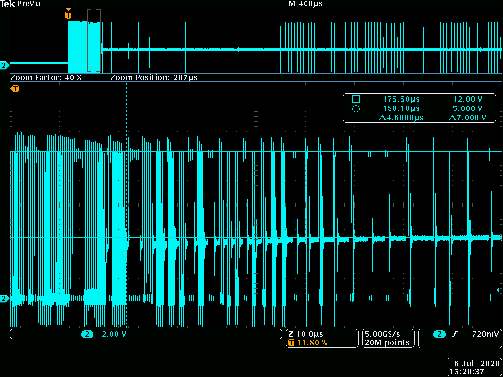
    This is a scopeshot of a good regulator on the output switch node from startup to steady state:

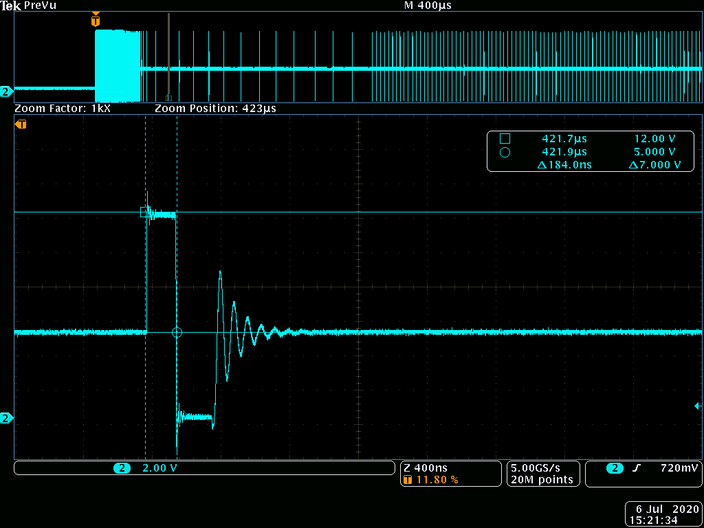
    And this is a zoomed in of steady state where its in light load mode.

    The output of a bad regulator:

    Enyu

  • Hi Enyu,

    Thanks for the further information. Considering the output is still sitting at 0.6V or 1.3V, it would be good to see SW node waveform and ideally inductor current as well, if possible.

    Can you briefly describe the timing of the VIN and EN signals? Is VIN already available when 5V EN trigger is triggered? Can you share a schematic?

    Regards
    Amod

  • Hi Amod,

    The "bad scopeshot" contains waveforms on 2 channels, one of them is the SW node, and other other is at the output. They just spike up upon enable, and rises to a 0.6 or 1.3V steady state. They look identical, probably cause theres insignificant current. I did check that the inductor is indeed 2.2uH with a 4-wire LCR meter. Did not get any current measurement for that.

    EN turns on after Vin. Probably in the 5-100ms range. On that note, I did try to do an experiment where I turned on EN without any VIN present, and that does not seem to break a good regulator - even leaving in that state for more than a day.

    Heres the schematic:

    PP3V3 goes to an MCU that takes about ~20mA and has another 5x 0.1uF caps on that rail.

    Regards,
    Enyu

  • Hi Enyu,

    So, there is no switching at the output in the bad regulator waveform case. And, the settled SW node and Vout value is 0.6V/1.3V? Can you check if VIN is still providing the voltage as expected during this bad case? I cannot see the schematic you attached - perhaps you need to attach it as a file.  

    Thanks for sharing the information on EN timing. We need to look at this more. You are saying that when VIN is present and then EN comes up after 5-100ms, the output is always bad (0.6V or 1.3V)? Is the same IC (when VIN is present and then EN comes up - bad case) able to regulate when EN comes up first before VIN? or are you trying with a newly replaced IC?

    Regards,

    Amod

  • Hi Amod,

    Yes there is no switching at the output of the bad regulator. The settled SW node and Vout value is mostly ~0.6V, tho I've seen 1.3V before. Vin is still provided.

    Yes - VIN is present and then EN comes up after 5-100ms, the output is always bad (0.6V or 1.3V). 

    It is not the same IC for the case where EN comes up before VIN. I was just trying various ways to see what will break a good regulator to figure this problem. In this case, the good IC was still operating fine.

    Here is the schematic:

    Thanks,
    Enyu

  • Hi Enyu,

    In the case where VIN is present and then EN comes up, with that same IC (bad output earlier), if you change the order (EN before VIN), does the output regulate? I am trying to confirm if IC is damaged. It is hard to explain why swapping VIN and EN signals is not causing the issue.

    Can you please share the inductor part number? You may be at the edge of inductor current saturation during startup - I see 600mA+ currents in my no load simulation in TINA-TI and this can vary depending on load and output cap values. Inductor current peak can exceed the saturation current rating and cause increased current through the IC. If the inductor saturation is hard and its value falls off quickly with current, then the IC may not be able to protect the FETs using the current limiting feature built inside the IC. It is safe to replace with an inductor which has a saturation current limit greater than the current limit of the IC (max 1.35A). Inductor current waveforms in the bad case setup might give us more insight.

    At the output, the LDO datasheet suggests using 1uF caps at the input and output. I assume the layout is such that the 1uF cap (at TPS62173 output) is close to the VIN pin of the LDO. EN voltage level high is 1.2V - So, around 100us or so during startup of the TPS62173, the LDO will turn on and its load will start drawing additional current. You can make sure this operation is as expected and there are no issues at the LDO side.

    Regards,

    Amod

  • Hi Amod,

    The output of the bad regulator will still not regulate swapping VIN and EN order.

    The inductor is Taiyo Yuden MBKK1608T2R2M. 2.2uH, 750mA current rating, 520mA Saturation current, 345mOhm DCR max.

    Would an inductor of >1.35A saturation current be necessary? The intent here is for a buck regulator for small footprint on a lower power requirement. An inductor with high saturation current would take more much more space.

    No issues on the LDO side. 

    Here is layout if that helps:

    Thanks,
    Enyu

  • Attaching screenshot of layout again:

  • Hi Enyu.

    Looks like the IC is damaged then as swapping VIN/EN did not resolve the issue. Problem with saturation current (520mA) is during startup you could see much larger currents than the steady state condition. And, we want to ensure that there is sufficient margin for the saturation current. 1.35A is the max current limit but you can probably reduce a bit further to 1A which is the typical value. If you increase inductor to 3.3uH, you could do with slightly lower saturation current. I have not checked if you will get these in the size you are looking for though.

    Regards,

    Amod