This thread has been locked.

If you have a related question, please click the "Ask a related question" button in the top right corner. The newly created question will be automatically linked to this question.

LM3550: Not charging in fixed voltage mode.

Part Number: LM3550

Hi,

 Currently I am using LM3550 for my strobe project.

 I am using the same schematic as given by TI as reference design. The problem I am facing is when I am placing the LM3500 in charge mode with the indication LED on,

 The indication LED goes off after the CAP voltage reaches roughly 2.8V. The capacitor used is 0.5F 5V.

 My I2C commands and steps are as follows.


  STROBE_SetLow(); // strobe pin low.

   I2C1_Write1ByteRegister(LM3550,CURRENT_CONTROL_REGISTER,0xC0);

   I2C1_Write1ByteRegister(LM3550,OPTIONS_REGISTER,0x00);                                                // 16ms Flash

   I2C1_Write1ByteRegister(LM3550,GENERAL_PURPOSE_REGISTER,0x92);                           // Place the LM3550 in fixed voltage charge mode (5V), indication LED on.

While(1)

{

              I2C1_Write1ByteRegister(LM3550,GENERAL_PURPOSE_REGISTER,0x14); // send the flash command

             __delay_ms(16); // delay

              I2C1_Write1ByteRegister(LM3550,GENERAL_PURPOSE_REGISTER,0x12); // put the LM3550 in change mode 5V

             __delay_ms(1000);

  }


With the above steps I don’t see the flash.

But if I set the FGATE =1, and put the LM3550 in optimal changing mode then I could see the flash.


Why LM3550 is not charging the capacitor to the programmed voltage.


Thanks in advance for your support.


Ramdas.

  • Hi Ramdas,

    The super capacitor need time to be charged to target. Please refer to section 7.3.6 in the datasheet. 1000ms isn't enough.

    But if you set the FGATE=1, it means the flash can take place even if the charger haven't finished.

    BR,

    Robin

  • Hi Robin,

    Thanks for the replay.  that code was just to show how i was placing the LM3550 in charge mode.

    i have waited for a long time, say one hour without giving the flash but still the CAP voltage did not reach 5V.

    the test code is as below.

      STROBE_SetLow(); // strobe pin low.

       I2C1_Write1ByteRegister(LM3550,CURRENT_CONTROL_REGISTER,0xC0);

       I2C1_Write1ByteRegister(LM3550,OPTIONS_REGISTER,0x00);                                                // 16ms Flash

       I2C1_Write1ByteRegister(LM3550,GENERAL_PURPOSE_REGISTER,0x92);                           // Place the LM3550 in fixed voltage charge mode (5V), indication LED on.

      while(1)

    {

       // do nothing wait and see the CAP voltage/

    }


    since the voltage did not built, for testing purpose i set the FGATE to 1 and then started seeing the flash.

    form the above testing code i noticed the indication LED is going off once the CAP voltage reaches roughly 2.8 to 3V.  By any means LM3550 is getting reset?

    please let me know what could be the problem. 

    thanks and regards,

    Ramds

  • Charing.xlsxHi Robin,

    to give you more information.

    if i increase the input voltage to 5V the charging is also 5V.

    i am attaching the charging wave details for both 5V and 3V input.

    input is 5.3V

    Input is 3.3 V

    thanks and Regards,

    Ramdas

  • Hi Robin,

    i waiting for you inputs. 

    is this product LM3550 still supported by TI?

    we are in a urgent to close the project. pleas give some light on using this LM3550 for our strobe project.

    thanks and regards,

    Ramdas

  • Hi,

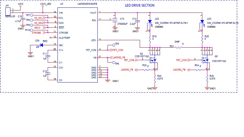
    Would you mind providing your schematic for detailed analysis?

    Besides, according to your description that indication LED is off, it seems the VIN also has issue since this is just a current source, independent with the other parts. So please measure the VIN during the test.

    Robin

  • hi Robin

    here is the schematic for the same. 

  • Hi Ram,

    What's the part number of C13? Because I want to know how you connect the BAL pin with the capacitor (Vbal=1/2*Vout).

    Robin

  • hi Robin,

    we do not have a balance pin we use 0.5F ,5V, 2 lead capacitor.

    thanks and regards,

    Ramdas

  • Hi Ram,

    Your schematic seems correct except the BAL pin. This device utilizes VOUT and BAL pins to control the output voltage, thus I think BAL should connect to the middle part of two super-cap.

    I do not have an evaluation board at present, so could you help do some bench test to verify my doubt? Please add another super cap and connect the BAL pin to the right place.

    Thanks!

    Robin

  • Hi Robin,

    thanks for the response.

    below is my steps and results.

    I tried with two 1F, 2.5V  connected in series so that the effective capacitance would be 0.5F and voltage would be 5V(2.5+2.5).

    In this way, I connected the center pin to the balance pin of LM3550.

    still it behaves  the same way. 

    thanks and Regards,

    Ramdas 

  • Hi Ram,

    If so, I need to have a discussion with my colleagues. Please wait for my reply.

    Robin