A related question is a question created from another question. When the related question is created, it will be automatically linked to the original question.
If you have a related question, please click the "Ask a related question" button in the top right corner. The newly created question will be automatically linked to this question.
[FAQ] TPS650864: [Regulator] is shutting down or measuring x% lower than expected - what is the cause?
TPS650864, TPS650860, and TPS650861 all have power fault monitoring for system protection. If any of the enabled regulators exceeds the power fault threshold during normal operation, the PMIC will trigger an emergency shutdown – disabling all regulators simultaneously in order to try to protect the system. A common issue during debug is to notice a rail shutting down due to emergency shutdown but thinking it is the cause, rather than the effect. This can help to identify what is the cause of the emergency shutdown.
During an emergency shutdown, PMIC shuts down all rails simultaneously. After that, PMIC will reload the OTP memory and check the CTL pins for what to do next. If the CTL pin used for enabling the PMIC is tied high, the PMIC will restart the power up sequence and continue looping. For example:
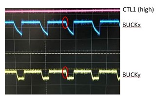
In this example, at the point where the red circles are, the part senses that any one of its outputs is not at the correct power good threshold and started emergency shutdown. After emergency shutdown has completed, it sees that the system has set CTL1 high and it begins the power up process again.
This behavior often leads to two different diagnosis:
BUCKx is shutting down, something must be wrong with BUCKx
In this example, BUCKx and BUCKy are both shutting down at the same time due to emergency power fault of BUCKz not pictured – BUCKz was enabled by the OTP but the external components were not populated so the PMIC initiated a power fault when it failed to reach powergood within 10 ms
The 10 ms mask is a clear way to confirm this is the expected issue – if the cycling occurs at approximately 10 ms periods, then it is most likely a regulator not reaching powergood.
BUCKx is measuring at 0.75V instead of 1V
A digital multimeter will read an average voltage. In a case like above, it gives a voltage proportional to the location of the buck within the overall sequence. The first regulator in the sequence will be off for a very short time, while bucks later in the sequence have more opportunity for the output to decay.
Next, to identify where the fault occurred, read the SHUTDNSRC, PWR_FAULT_STATUS1 and PWR_FAULT_STATUS2 registers to identify where the PMIC is detecting a fault and focus the debug efforts there.
For cases where these cannot be read and the issue is occurring during the power up sequence, the best course of action is to take scope shots of the complete power up sequence to confirm it matches the expected sequence from the datasheet or app notes. If a regulator fails to turn on – this can either be the regulator to focus on or the regulator before this may be having an issue.
For cases where these cannot be read and the issue is occurring during normal operation after power up, the best approach is to check the voltage on each regulator with an oscilloscope during the fault – use an oscilloscope to trigger on one of the GPOs (they are set low with a good edge), check the voltage of each regulator right before the GPO goes low – the abnormal rail often shows a rising or falling behavior before triggering the fault.