This thread has been locked.

If you have a related question, please click the "Ask a related question" button in the top right corner. The newly created question will be automatically linked to this question.

[FAQ]: Ideal Diode controller vs ORing Controller?

Other Parts Discussed in Thread: TPS2410, TPS2411, LM7480-Q1, LM5050-1, LM5050-2, LM74700-Q1, LM7481-Q1

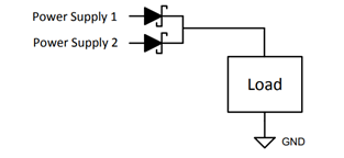
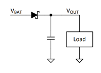
What is the difference between an Ideal Diode Controller vs an ORing controller?

RELATED PRODUCTS: LM74700-Q1, LM7480-Q1, LM7481-Q1, LM5050-1, LM5050-2, TPS2410, TPS2411

  • Technical Background:

    Power Schottky diodes are conventionally used for ORing power supplies and reverse battery protection or reverse polarity protection.

    Figure 1: ORing Power Supplies using Schottky Diodes

    When ORing two or more power supplies rails, Schottky diode blocks reverse current from flowing into a failed supply, a disconnected power supply or sudden drop in power supply voltage. Fast reverse current blocking is key requirement for ORing power supplies. Conventional method for ORing two power supplies using Schottky diodes is shown in Figure 1.


    Figure 2: Reverse Battery Protection – Schottky Diode

    Reverse battery protection implemented using Schottky diode is shown in Figure 2. Reverse current blocking is required to prevent hold-up capacitor banks on the output from discharging during various input transients including transient negative voltage at the input. Reverse current blocking naturally provides protection from reverse input polarity conditions to circuits and components connected on the output. Reverse polarity conditions can be static, during reverse connected battery or power supply wires or dynamic due to inductive load switching.

    Note that ORing two supplies in systems where input mis-wiring or reversing supply input cables is not possible, reverse polarity protection is not required.

    Comparison:

    Both the ORing Controllers and Ideal Diode Controllers drive an external N-Channel MOSFET to emulate the function of an Ideal diode with very low forward drop (8mV - 22mV) and block reverse current flowing from output to input side. Due to reverse current blocking functionality, components and circuits connected on the output are naturally protected from reverse connected battery or input polarity conditions.

    However, the controllers themselves may not be protected from reverse input polarity conditions. Since the controllers operate by taking power for internal biasing from the input to GND, ESD diode exists from GND to INPUT. Controller’s internal ESD diode gets severely damaged during input reverse polarity as it conducts as soon as INPUT voltage swings negative with an exponential increase in current.

    Ideal Diode Controllers are basically ORing Controllers with integrated reverse input polarity protection or reverse battery protection. Ideal Diode Controllers protect rest of the circuit components from negative voltage and also protect themselves from damage due to reverse input polarity conditions.

    Figure 3 shows the functional block diagram of LM74700-Q1 (Section 9.2 in LM74700-Q1 Datasheet). Reverse protection logic operates from ANODE to GND to protect LM74700-Q1 from reverse input polarity conditions.

    Figure 3: LM74700-Q1 Functional Block Diagram

    However ORing Controllers such as LM5050-1 does not have the reverse polarity protection integrated and required external components as shown in Figure 4. Diode D4 protects the controller from reverse input polarity conditions. MOSFET connected between D4 and GND allows low IQ operation when disabled.

    Figure 4: Reverse Battery Protection using LM5050-1