This thread has been locked.

If you have a related question, please click the "Ask a related question" button in the top right corner. The newly created question will be automatically linked to this question.

BQ24133: radiatedd emission fails

Part Number: BQ24133
Other Parts Discussed in Thread: PMP4397

Hi,

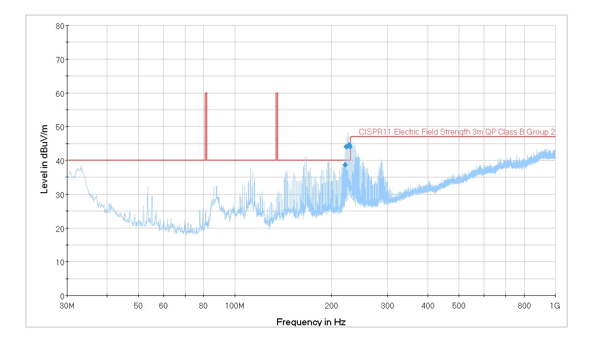
        I design a portable product with BQ24133, but it fails to pass the radiated emission test. The result and my circuit are as follows:

6281.Power.pdf

 There is an adapter with a 1.3m long power wire to plug in my product to recharge the battery in it. As the emission exceeds the threshold at about 225MHz and 225MHz corresponds to about 1.3m wavelength, I guess the long wire on the adapter forms an antenna. I search the forum and find several posts, and the suggestions are follows: 1) add a resistor at BTST pin; 2) add snubber circuit at SW pin. Will these work for my problem? or is there any other solution?

        Is isolating the AGND and PGND necessary? If so, the reference terminal of the battery should be connected to PGND. The battery powers the rest part of the system, then how should I isolate their grounds?

  • Hi,

    Both solutions you found work for this issue. I would also suggest to make the layout of the converter as small as possible, with input caps close to high side fet (PVCC). The inductor, sense resistor and output caps as close as possible to the SW node. The RC snubber is a quick way to find out if it works, as it is a shunt circuit, you can scratch the surface of the board and connect it to a GND net.

    If you were to update the layout, apart from adding the RC snubber, I suggest also adding a 0 ohm footprint in series to BTST to debug EMI.

    Regards,
    Steven

  • Hi, Steven,

    thank you for your advice. I will try these solutions in my next PCB version.

  • Hi, Steven,
    Do you think separating the AGND and PGND and a connection of them just beneath the thermal pad are necessary? If so, I think the negative terminal of the battery should be connected to PGND. As the battery powers the subsequent circuits of the system(SGND), how should I connect the PGND to SGND, also the VBAT to SVCC? Is any isolation necessary?
    I have read the reference designs on the TI website, but haven't get any clue.
  • Hi,

    Yes, just connect AGND and PGND underneath or close to the IC. Anything high current should be placed at PGND, like the battery. Also, yes, SGND should be connected to PGND at some point to have the same point of reference for all your circuit. Do you have an updated schematic?

    Regards,
    Steven
  • Hi,

        I haven't updated the schematic, but I'm doing some testing. As same as the reference design on http://www.ti.com/tool/pmp4397, I add the snubber circuit with R 10ohms and C 0.01uF.

    I can indeed observe the radiated emmission attenuation with a spectrum analyzer, but there is still a problem.  From the application note of ROHM semiconductor below, the Power of R is calculated by  C*Vin^2*f

    where C is the snubber capacitor value, Vin is the input voltage, f is the operating frequency of BQ24133

    Snubber circuit for Buck Converter IC.pdf

    with C = 0.01uF, Vin = 10V, f = 1.6MHz, the power of R is 1.6W, which is so large a power. From the BOM of the reference design, the snubber R is CRCW080510R0JNEA with a 0.125W power rating, much smaller than 1.6W. Is that OK? Will the R be destroyed in a long time charging process? Or the power of R cannot be calculated with the formula in the attachment?


  • With 10ohm and 0.01uF snubber, when the charging is in process, I touch the inductor and the snubber resistor, they are both very hot. Can any other values for R and C work? How should I calculate them?
  • There is a quick way of determining the snubber size. Follow the blog post: e2e.ti.com/.../calculate-an-r-c-snubber-in-seven-steps

    Regards,
    Steven
  • Hi,

       I've updated my schematic , adding a RC snubber to SW and a 0 ohm resistor to BTST. Are there any other problems?

    6523.Power.pdf

  • Hi,

    This looks good. For the resistor power rating, you only need to make sure that it can handle a power spike for a very small amount of time. An 0603 1/4W resistor should be able to handle it.

    Regards,
    Steven
  • Hi,

        As the power dissipated by the resistor is proportional to the value of the capacitor in the whole charging process, P=C*V^2*f, with a high input voltage and capacitor value, the power  dissipated by the resistor will be a large one. For example, with C = 0.01uF and supposing V = 10V, then P = 1.6W in the TI reference design PMP4397. I don't think a 0603, or even 1206 resistor can satisfy the power ratio. When I use a 0603 resistor to test, it will be quite hot quickly.

        However, for my value R=4.7ohm and C = 390pF, a 0603 resitor will work at the cost of a lower EMI attenuation.

  • You can try to accommodate the largest resistor you can fit on your design, this way you can make sure there are no problems. Also take into account that since the converter is integrated and all the current passes through the IC, the bq24133 will generate heat, as well as the inductor. This heat may transfer onto the resistor as well.

    Regards,
    Steven