This thread has been locked.

If you have a related question, please click the "Ask a related question" button in the top right corner. The newly created question will be automatically linked to this question.

LMV431: V REF REPLACEMENT IC

Part Number: LMV431
Other Parts Discussed in Thread: LM25085, TL431, TLV431, , LM321

Hello,

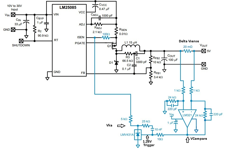
We would to use TL431 (TL431ACDBZR) instead of LMV431A in the attached schematic for current limit circuit as noted in blue added to LM25085. can you please advice if that is possible?

In Addition, if using TL431, is it correct to short the cathode to Vref to get 1.24v in this circuit to get the same result as with LMV431A (as the TL431 alternative circuit on the left side)?

By replacing to TL431, Is it possible also to take out from this circuit R1, R2, R3 and C1?

Thank you in advance,

Barg

  • Hi Bar Greidy,

    I do not think this is possible because the LMV431A is a 1.25V reference device while the TL431 is a 2.5V reference device.
    It is not possible to get a regulated 1.25V from the TL431 because shorting the REF pin with the cathode will give you 2.5V if properly biased.

    Is there a particular reason on why you want to replace the LMV431A?

    -Marcoo
  • Hi Marco,

    Thank you for your reply.

    Yes I missed the V and referred by mistake to TL instead of TLV431 (1.24v ref)... the reason, we would like to reduce the total parts number. As to that, can we use INA... instead? I added a schematic with INA.

    Can you please advice if possible to use this configuration as I noted with INA to limit the LM25805 current as the origin circuit with the LMV431 and the opamp? or anything needed to change?

    Regards,

    Barg

  • Hi Barg,

    Back tracking a bit, you need R1 for biasing or else the lmv431 does not work. R2/C1 seem to be used as a compensation network so you would have to test your system to see if you need them or not.

    In terms of replacing the amplifier network with a INA, this works as well but you lose the 1.25V threshold of the lmv431. Instead this is now highly dependent on the INA output relative to the voltage on Isen + a variable diode drop. You could replace the diode with the a lmv431 and achieve a similar results to the original design.

    -Marcoo Z
  • Hi Marco,

    Thanks for your reply.

    If using the lmv431 original design, can you please advice how to change the current limit th and with which components? as for this one it is 2.5A threshold.

    If using a 10mOHM as the shunt resistor how to make the calculation accordingly to get the desired current limit of 5.5A limit for example?

    Regards,

  • Hi Barg,

    The trigger is set by the internal bandgap voltage reference of the LMV431 which is 1.25. The LMV431 acts like an open drain comparator so when the REF pin is below 1.25V then Vka will be the same voltage as the voltage on ISEN. If REF is triggered because it is higher than 1.25V then Vka will pull low bringing ISEN down. The trigger voltage is based on the output of the LM321 amplifier. The (delta Vsense) * (gain of LM321) = output voltage of the LM321 which is then used for comparisons. Delta Vsense = (Sense Resistor) x (Current Limit).

    When you use the INA but remove the LMV431, then you have the Vcompare output voltage but you do not have the open drain comparator ability. I would say to look into current sense devices with built in open drain comparators if you want to save in parts.

    -Marcoo

    ~~~~~~~~~~~~~~~~~~~~~~~~~~~~~~~~~~~~~~~~~~~~


    If you feel this is resolved, please selected Answered.

  • Hi Marco,

    Well noted and thank you for your detailed answer!

    Can you please advice if there is any way to add a fault signal led (2V-3v, 10ma) or properly working led to this ic circuit to one of the places?

    Regards,

    Barg

  • Hi Barg,

    Look at figure 28 of the LMV431 datasheet. It shows a setup that has a high and low voltage monitor limit. In your situation, you don't need a high limit so you can remove one of the LMV431 and just use the low limit to trigger when you need it too. You already have something similar to the low trigger in the diagrams from the previous messages. So if you add a LED in series with the cathode of the LMV431, it should work.

    -Marcoo

  • Hi Marco,

    I will look at your suggestion, Thank you for your assistance.

    Barg