


Hi There,
I am having an issue with a TPS7A1633DGNR part (henceforth LDO)
I am using it as a local supply for some SOC monitoring circuitry supplied by a multi-cell pack in a multi-pack power supply.
When I turn off an AC connected power supply that is far removed from this, the LDO appears to latch up and outputs a relatively hi-Z ~150mV to 100mV instead of 3.3V. I expect turning on/off the AC power supply will generate some common mode noise which may get injected into the system, however I have no problems with any other devices.
This condition does not clear until either input power is removed, or the enable pin is brought low/high again which I can do with the circuit/opto shown.
This problem existed before the remote disable circuit was implemented, so I doubt that is related to the cause of the problem.
I have scope shots showing input power is steady, and output drops.
Current draw is quite low < 5mA.
Probing the enable pin, I can see it sits at the same voltage as the input pin, so it does not appear to be a problem with the enable pin.
Using a thermal camera, I can see the part is not hot, so it does not appear to be in a current limit mode (?).
I have tried increasing the output capacitance, but that does not help the problem.
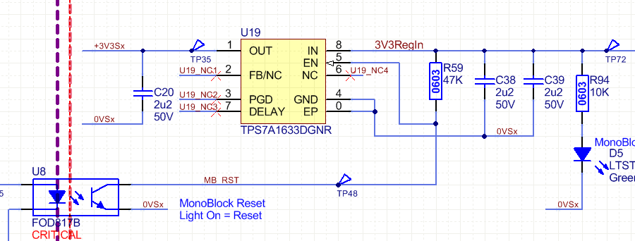
Here is the schematic;
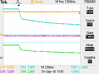
Here is a scope capture somewhat showing the problem, capturing the glitch occurring is somewhat challenging however it can be seen happening on two regulators that are supplied by different batteries at the exact same instant.

Ch1/yellow: regulator #1 input, 5V/div
Ch2/blue: 3v3 regulator #1 output, 1V/div
Ch3/purple: regulator #2 input, 5V/div
Ch4/green: 3v3 regulator #2 output, 2V/div
Any help that can be provided would be appreciated.
Thoughts?
Thanks,
Bryce
