This thread has been locked.

If you have a related question, please click the "Ask a related question" button in the top right corner. The newly created question will be automatically linked to this question.

TM4C1294NCPDT PoE Design

Other Parts Discussed in Thread: TM4C1294NCPDT, TPS2375EVM, TPS2375, TPS23750, TM4C129ENCPDT, TPS23753A

Hi All,

I have made a custom design with TM4C1294NCPDT and TPS2375PW-1. I tried to combine the reference designs found in their datasheets.
But it seems that I made a principle design mistake, as it sporadically worked and didn't work, and after a while the MCU became faulty.

The symptoms were the following:

  • During startup there were some small sparks (only noticeable in the dark) at the Ethernet pins of the MCU.
  • The MCU was heating with the udpEcho / tcpEcho samples.
  • The Ethernet link LEDs lit, but The DHCP communication was sporadically faulty.

Below are the design parts which I think contain the mistake (the power supply parts worked fine):

  • RJ45 connector side of the LAN transformer:

  • The MCU side of the LAN transformer:

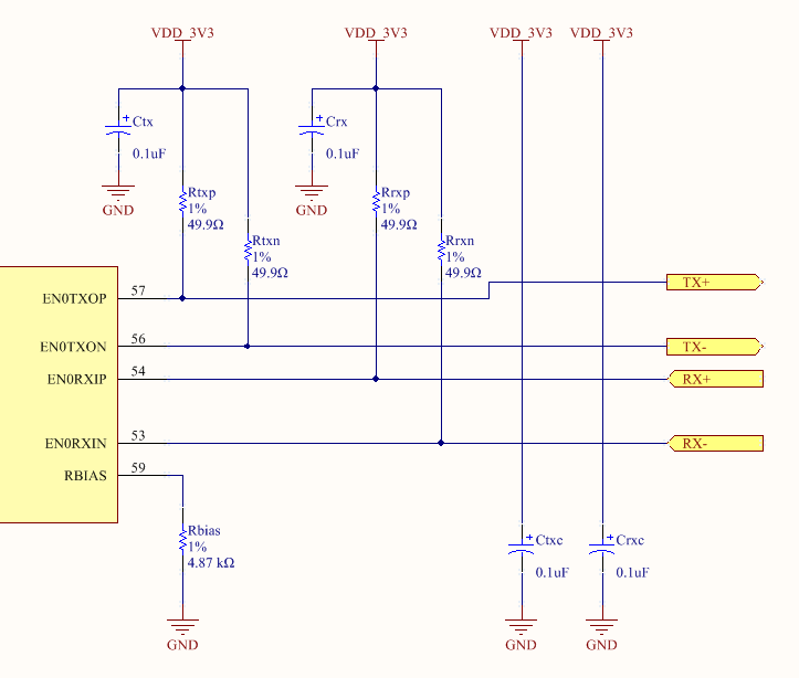
(Note that the TX+/TX- nets are connected to TD+/TD- and the RX+/RX- nets are connected to RD+/RD-n, and GND isconnected to PGND )

Could someone please take a look at the design and tell what's wrong? I would be very grateful.

Thank you,
Gergely

  • Hello Gergely,

    Which TPS2375PW based reference design is this?

    Regards
    Amit
  • Hi Amit,

    it's on the first page of www.ti.com/.../tps2375-1.pdf

    Regards,
    Gergely
  • Hello Gergely

    I am moving it to the PoE Forum, as the issue is at the power stage and would require more expertise in the power stage.

    Regards
    Amit
  • I see now that my design is missing a "modified" Bob-Smith termination. But will it solve the problem? Can the symptoms I mentioned originate in that, or is there something else as well?

    Thanks,
    Gergely
  • Hi Gergely,

    It sounds like the PoE functionality is working as the power is being delivered to the MCU after successful detection and classification? Is the MCU being powered by PoE via DCDC converter? Is the converter stable? The power and data should be separate from each other and it seems like you are having trouble with the data side? Have you tried testing on the TPS2375EVM? There is a port where you can pass through data. This may help narrow down whether there is an issue on the board with assembly or component value.
  • Hi Darwin,

    thank you for your response.
    Yes, PoE functionality is working fine, the MCU is powered by DC/DC converters, and the converters are stable.

    I've been thinking about this problem more, and what I found is the following:

    During the device is being detected and classified, the RTN pin of TPS2375 is not being driven, so we can say that GND and VDD are on the same levels on the whole board, which is the VDD_POE.
    But when TPS2375 begins the normal operation, RTN falls about 48V (= the PoE power). But the DC/DC converters work relative to RTN, so we can say, VDD_3V3 falls 48V and rises 3.3V (so falls about 45V).
    But VDD_3V3 is connected to the center pins of the transformer on the data side, so this 45V fall may generate some real undesired transients.

    What do you think of this? This may explain the sparks at the MCU.
    I'm a software developer and have very little experience in electronics, so it can be that I see something very wrong.

    Thanks,
    Gergely
  • Hi Gergely,

    How is the TD+/TD-/TDC and RD+/RD-/RDC circuitry on the PoE side schematic connected to the TX+/- RX+/- circuitry on the MCU side schematic? Do you have the full schematic? Thanks!
  • Hi Darwin,

    here is the top-level schematic:


    What you don't see here is that PGND and GND are connected as well.

    Hope this helps.
    Gergely

  • Hi Gergely,

    The PoE PD has its own inrush current limit such that the turn on of the PD internal FET will not be fast. In addition, utilizing the PG of the PoE PD will keep the power supply off until the PD internal FET is full on (GND =0V). I don't believe this is a PoE side issue.

    Looking up the data transformer online says it can do PoE.

    Amit,

    Can you confirm the TM4C1294NCPDT PHY can be used with the HX2019 data transformer in this configuration?

    Otherwise, it may be an incorrect connection or component on Gergely's board.
  • Hi Darwin,

    I think you might be right, and TM4C1294NCPDT might have problems with HX2019. I made another board with a modified B-S termination and with the buck converter reference design of TPS23750 (in which the DC/DC converter works relative to the positive rail), and got almost the same results.

    Do you have a suggestion, which PHY to use with PoE 10/100 that is proven to work?

    Thank you,
    Gergely
  • Hello Darwin, Gegely,

    We have used HX1198FNL on the launchpad with an external PoE splitter and not seen an issue

    Also there is a TI Design for PoE which uses Abracon ARJP11A-MASA-B-A-EMU2 and TPS23753APW with TM4C129ENCPDT and it does not show any such failure on multiple plug-unplugs.

    Regards
    Amit
  • Hi Amit,

    could you send me the link for that TI design?

    Thanks,
    Gergely
  • Hello Gergely,

    We are in the process of publishing the design. It would take 2-3 weeks before it comes online on www.ti.com

    Regards
    Amit
  • Hi Amit, Darwin,

    as I see TPS23753A is specially for isolated design. Could this be the key that the PHY of the TM4C129 MCU requires an isolated power supply and does not work well with a buck topology DC/DC? Using an external PoE splitter is also kind of an isolated design, if I'm right...

    Gergely
  • Hello Gergely

    I have used an PoE EVM which has a non-isolated power supply and connected it to a LaunchPad and seen no issues. Of course I have not done extensive testing, but only a proof of concept

    Regards
    Amit
  • Hi Amit,

    then I have no idea what the problem could be on my board, as the MCU is connected to almost nothing but Ethernet, as I have the other parts with connectors and on an other board which is disconnected right now.
    Anyway, I look forward to seeing the PoE design with TM4C1294 that you mentioned.

    Regards,
    Gergely
  • Hello Gergely

    Sure. I will update the forum post as soon as it comes online.

    Regards
    Amit
  • Hello Gergely,

    The design just got released.

    www.ti.com/.../TIDM-TM4C129POE

    Regards
    Amit
  • Hi Amit,

    digital CAD files, in addition Altium Designer... I can't find the words :)
    Thank you very much!

    Gergely
  • Hello Gergely

    Thanks for being patient. it took us more time than anticipated. Do let us know your feedbacks on the same

    Regards

    Amit

  • Hi Amit,

    no problem. It's possible that I will let the new board made only in a few months anyway, as I have other expenses now.
    I will post here how it goes.

    Regards,
    Gergely
  • Hi Amit,

    I just got the new board and it works like a charm so far (at least the MCU/Ethernet/PoE part).

    One thing I recognized I did wrong in the previous design was that I connected an 1.2V supply to VCC of the MCU. I think this explains why the MCU was heating.

    The other thing were the small light beams at the Ethernet pins of the MCU during startup. What has changed related to this is that the new board uses an isolated design instead of a simple buck topology. I think this could be the reason, but I'm not good in analog electronics, and I don't understand the whys.

    Regards,
    Gergely