This thread has been locked.

If you have a related question, please click the "Ask a related question" button in the top right corner. The newly created question will be automatically linked to this question.

TPS23861: 4-6 port Network switch, with 4 PoE ports for PoE-IP cameras. Design review

Part Number: TPS23861
Other Parts Discussed in Thread: TIDA-00465

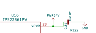
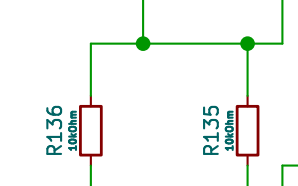
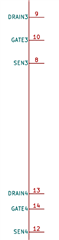
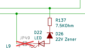
I'm designing a network switch, that has four PoE enabled ports (to power four PoE-IP cameras). I'm using the TPS23861 as the PSE device to supply the necessary power. The supply power to the PSE would be 46V to 54V.

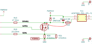
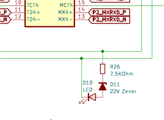
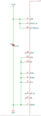
I tried following the design of the TIDA-00465 reference guide for the single port and then replicated it for four ports accordingly.

Can you please help review the designs and advise if anything should be connected otherwise.

Thank you for all the help.

Attachment : NetworkSwitch.pdf

  • Hi Mo,

    I will review and provide comments by end of the week. Thanks!

    Regards,

    Brandon

  • Hi Mo,

    Please see my comments from review:

    1. I would recommend placing the slow blow fuse between your FET and the 47ohm drain resistor. This provides better protection to the actual IC.

    2. If running compliance, add a jumper selection between your LED and low side. The LED current consumptions sometimes can cause Sifos failures if running compliance only.

    3. If this is a proto build, recommend adding DP pullup resistors for testing purposes (SDAI, SDAO, SCL, RESET, SHTDWN)

    4. Add .1uF bypass cap per datasheet requirement on Vpwr

    5. SM6T10A is not rated for PoE operation. TVS needs to be a minimum reverse standoff voltage of 58V and a max clamping at 95V.

    6.Self check Q1-Q4 meet design requirements:

    Regards,

    Brandon

  • Thank you, Brandon. You are the best.

    I'll go over them next week and implement accordingly. Appreciate all the help.

  • Hi Mo,

    No problem! Feel free to reach back out with any concerns. 

    Regards,

    Brandon

  • Hi Brandon,

    I was finally able to get around to all your suggestions. Please see attached.

    I ended up needing two TPS23861. We are hoping to use one of the ports as a passive PoE (I understand the TPS23861 allows manual mode on any of the ports). However, I believe it needs the I2C interface. Can you please double check my I2C connections too.

    Further, wanted to see if my A3 pin connections look alright? In order to be able to address both the TPS23861 pins on the I2C bus independently. 

    Finally, wanted to get your opinion on the data connections to the RJ45. I realized in my previous schematic, I did not connect the B+, B- and C+, C- pins correctly. If you can please review my corrections.

    Thanks again for all your help.

    1055.NetworkSwitch.pdf

    6735.PowerSupply.pdf

  • Hi Mo,

    Thanks for reaching out!

    Our PSE expert Brandon is traveling now. Please expect a delayed reply. Thanks for your patience.

    Best regards,

  • Thank you Diang, for the heads up.

  • No problem. Thanks for your patience.

    Best regards,

    Diang

  • Hi Mo,

    Thanks for your patience, as this was not in my queue since our team responded previously, so I apologize for the long wait. I still wanted to add my comments in the chance they are still applicable. 

    I ended up needing two TPS23861. We are hoping to use one of the ports as a passive PoE (I understand the TPS23861 allows manual mode on any of the ports). However, I believe it needs the I2C interface. Can you please double check my I2C connections too.

    TPS23861 can be used as "passive" where no I2C control is necessary, this is known as autonomous mode. If you wish to contorl the device from the host side you will need I2C control. I would not recommend operating in manual mode, and rather recommend operating in semi-auto mode if you wish to keep host control. Please reference datasheet for the differences in the two modes. 

    Comments from schematic review:

    1. Check your bypass cap on Vpwr, should be rated for 100V, 50V is not sufficient.

    2. Your I2C pullups might be a little weak. I usually recommend 4.7k or 3.3k but 10k should be okay as well.

    3. For unused channels, ground SENx pins, float the GATEx pins, and ground DRAINx pins.

    4. If you do not plan to use LED's for PG signal, you can DNP. If you wish to keep I recommend keeping jumper as the current consumption for the LED can lead to not passing compliance. So if you wish to run compliance you can remove jumper. 

    I am not an expert on data connections, so I would refer to our PHY team to comment on the data side. They look good to me, but again I am not an expert. 

    Your A3 pin connection is fine, I would recommend just grounding to use address 0x20.

    Regards,

    Brandon

  • Hi Brandon,

    I appreciate you getting back and thank you for going over my schematic in such a detail. Sorry, for the delay in getting back. Had another schematic to work on. But now back to wrapping up the POE portion.

    Please see my notes below, in the corresponding order of your comments:

    1. Thank you for catching the 50V by pass capacitor. Changed it to 100V.

    2. Thank you for suggesting 4.7k. Changed it accordingly.

    3. Thank you for catching that. Grounded unused SENx, KSENSB and DRAIN.

    4. I am not sure if I understood this correctly. I thought JP49 (opened jumper) would help serve this option. Where the jumper can be used to connect or disconnect the LED

    5. I did ground the A3 pin in the first TPS23861. However, to avoid having both the TPS23861s the same addresses, I pulled the other A3 high. Please correct me if anything.

    In reference to the autonomous mode and passive POE. In addition to regular PD devices we intend to power a passive PD device, which is not being able to be powered through active PSE devices that need hand shaking. We normally use something like this to power it. However, we want to use TPS23861 to power it instead. But from what I read in the datasheet and other forum posts here, the TPS23861's autonomous mode may not be able to power a passive PD device. But the manual/semi-automatic mode could. Please correct me if anything otherwise.

    There were two other things I wanted to run by you:

    1. Is 54V okay to power through PoE. Or should I bring it down to 48V. My understanding was the PD devices like IP cameras are able to handle 54V and will step it down to whatever they need.

    2. For the Passive PD device I mentioned earlier. It needs 12V instead of the 54V going to the other ports. I added an Oring circuit that along with a 12V supply through a Schottky diode could be used to power this passive PD device. So, that port has both 12V and 54V through the same TPS23861. Would that be an issue? Especially since the VPWR pin is getting 54V.

    I'm attaching the schematic here for reference.

    2746.NetworkSwitch.pdf

  • Hi Mo,

    Wanted to follow up on some of your comments: 

    1,2,3: Glad I could help!

    4. JP49 can be used to disconnect or connect the LED if used. I misunderstood the schematic as it showed the jumped, but showed as DNP, therefore this is good.

    5. That is okay to do, if you are using two TPS23861 devices on the same I2C bus, you can also connect the AOUT and AIN pins accordingly. No isses with your connection thought. 

    Additional questions:

    1. 54V is good! PoE operational range is 44-57V, therefore the PD can accept any voltage in this range and step down accordingly. 

    2. For passive or non-standard PD device, autonomous mode can not support since a handshake is necessary for powering any device that does not comply with IEEE standard. This is achievable in semi-auto mode and manual an and will really depend on the signature presented by this passive PD.

    Adding a 12V OR'ing circuit will cause issues with detection and classification cycles when connected to a valid PD device on this port. I would not recommend this approach as you will deadline this port...

    Regards,

    Brandon

  • Hi Brandon,

    Thank you for the prompt response. I appreciate you going over all the points. Just want to get back on the last comment.

    Adding a 12V OR'ing circuit will cause issues with detection and classification cycles when connected to a valid PD device on this port. I would not recommend this approach as you will deadline this port...

    Thank you for noticing that issue. Is there another way to run 12V PoE through the TPS23861. Should I have that TPS23861 only powered through the 12V supply. I mean, don't have the 54V option on that TPS23861 switch.

  • Hi Mo,

    Unfortunately, sourcing 12V to the PSE will keep the device in UVLO. Since 12V is well outside the operating voltage range it will be difficult to implement this without some kind of active control. If you have an MCU on board you could use this to control the switch to 12V, but I guess the better question is, how will you determine if the far end device is this passive PoE device? Is there some negotiation done on the data layer or do you plan to just inject 12V onto the port? This could cause damage if you connect to non-PoE devices and just inject voltage blindly.

    Regards,

    Brandon

  • Hi Brandon,

    Thank you for going over that.

    We could put a MCU on the board. But what is that we need to control?

    The switch and PoE we are building are going into individual machines, they won't be used for the general public. Hence, we could dedicate this switch for 12V injected PoE.

    Do I just need to turn on the MOSFET (Q6), in the schematic? If yes, we could just turn it on through a gate driver. Does that work out?0385.NetworkSwitch.pdf

  • Hi Mo,

    If it is a closed system and you control the connection, you can just use a gate driver to turn on Q6 (disconnect PSE). MCU would communicate with gate driver to control the turn on of that channel. The only concern is, your MCU would not have any idea when to turn the power on, how does the MCU know when the connection is being made? You would need to derive some method for detecting far end connection, or risk turning on blindly....

    If you turn on blindly, you could have some arching and safey considerations...hence, the benefit of PoE! Unfortunately, PoE can not operate at that voltage.

    Regards,

    Brandon

  • Good Morning Brandon,

    Thank you for getting back and advising on these issues in such detail. Appreciate all the help.

    My plan is to use the Oring circuit to enable or disable the 12V supply going to that port. The user can control the Oring through the onboard MCU and hence turn ON or OFF the 12V port.

    This is just a temporary solution, in the long run we'll get rid of the 12V device.