This thread has been locked.

If you have a related question, please click the "Ask a related question" button in the top right corner. The newly created question will be automatically linked to this question.

LMZ10505: LMZ10505 Part Failures experienced during system test and/or temperature testing of board

Part Number: LMZ10505

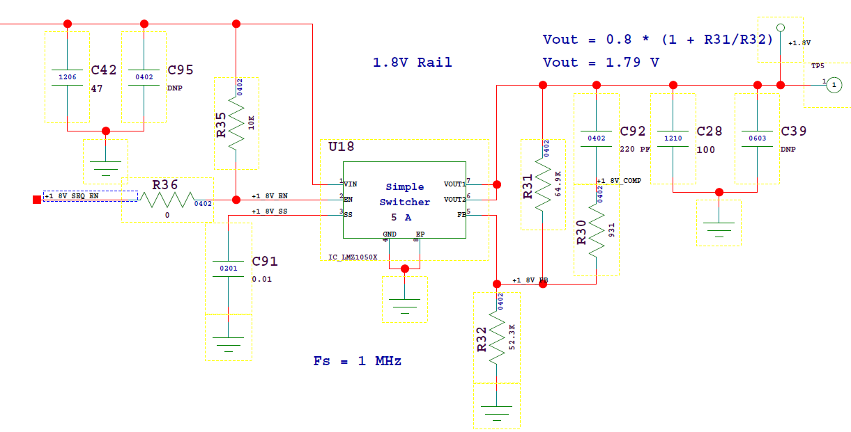
LMZ10505 being used to regulate from 5V down to 1.8V.

A number of these circuits have failed and it appears that the internals of the regulator have been damaged.

In a couple of cases it appears that the internals were damaged such that VIN is shorted to VOUT

In another case it appears that something happened causing the highside FET to always be turned on ---- causing the VIN to be tied to VOUT (but not switching)

We have captured some evidence of oscillation on the 1.8V output once we monitored the output with an oscilloscope over temperature testing --- a couple of hundred mV of ripple on the output at approximately 100KHZ

I'm attempting to verify compensation networks, component values, BOM items, but looking for any suggestions on items that could be tried to make the circuit more tolerant or forgiving.

Also ---- I'd welcome any input from folks with similar experience that could share their resolution to the issue.

Thank you.

  • Hi Dave,

    How well regulated is the power supply going into the LMZ10505? If the input supply has a spike that exceeds the maximum voltage rating of 6V on VIN, this could stress the HI-side FET and potentially cause EOS.

    Regards,
    Jimmy
  • The 5V input should be very well regulated. To date no more than a 100mV or so of noise or ripple has ever been observed on this around a 5V mean. Granted this is embedded in a large PCB with a many derived voltages. I will have to refresh my memory on the precise test points used for the 5V monitoring and its return to bolster confidence in the measurement. That being said --- I do not believe we have an excursion on the 5V input that would result in EOS.

    We have x-rayed some of the failures looking for compromised internals --- to date that has not pointed to any specific items. The modules internal connections appear to be intact --- so we are ruling out items like assembly stresses due to reflow profiles, etc.

    Curious --- what is the mechanism for sending back some devices for failure analysis?
    And is there any history of others experiencing failures with this device?
    I note a thread from a couple of years back that was 'locked' --- and I really could tell how that was ever resolved to see if the details fit.

    Thank you,
    Dave S
  • Hi Dave,

    Can you provide me with the schematic and PCB layout that you are using for 5V to 1.8V conversion application? The LMZ10505 has external compensation and can be affected by noise. If the regulator is unstable and in a noisy environment, this could result in improper operation of the LMZ10505.

    To send the parts in for FA, you can use this link to the customer return TI landing page.

    Regards,

    Jimmy 

  • Jimmy -

    here is a clip of the schematic portion of the circuit...

    I will see if I can release enough of the layout to you in order for it to be useful.

    What tools do you typically use?  Or what formats are useful to you?

    Thank you,
    Dave S

  • Hi Dave,

    You can send the schematic and PCB layout directly to me at j-hua@ti.com. For the PCB layout, I prefer Altium but you can also take snippets of every layer for the LMZM10505 circuitry.

    Regards,
    Jimmy
  • Also can you include the waveforms of Vin and Vout?
  • I will send a layer-by-layer snippet of the layout around the LMZ10505 to your email.

    I will also attach a plot of the output noise/oscillation ---

    Regards,
    Dave S

  • Hi Dave,

    I'll be closing this thread. If you have any further questions, you can direct it to my email.

    Regards,
    Jimmy