This thread has been locked.

If you have a related question, please click the "Ask a related question" button in the top right corner. The newly created question will be automatically linked to this question.

TMS320C6657: Boot magic address / Boot magic register

Part Number: TMS320C6657
Other Parts Discussed in Thread: TMS320C6655, , PROCESSOR-SDK-C665X

Hi TI

Can I find the encoding or any documentation on the format of the BOOT MAGIC register.

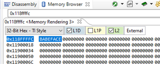
The only information i can find is on the test code of the evaluation board that this register has the address: 0x8ffffc

I have searched over all documentation but i can't find any description of such an important register of the the bootloader process

Can you please help. 

BR

Tam Tran

Vestas Wind System

  • Hi Tam,

    The Boot magic is a memory address (0x8ffffc)  which will have the address of the memory, where the code resides. And this code start getting executed when the core gets wake up. 

    For more info, please visit this link:

    https://e2e.ti.com/support/processors-group/processors/f/processors-forum/425551/problem-with-the-reading-of-the-chip-level-registers/1519565#1519565

    Regards

    Shankari

  • Hi Shankari G

    Can you please explain the statements in the code:

     #define BOOT_MAGIC_ADDR(x)  (MAGIC_ADDR + (1<<28) + (x<<24))

    The MAGIC_ADDR is 0x8ffffc. What does it means of the following statement: + (1<<28) + (x<<24)

    I suppose the statement handles more cores than 2. But why the "write_boot_magic_number" writes to the same MAGIC_ADDR "DEVICE_REG32_W(MAGIC_ADDR, BOOT_MAGIC_NUMBER);"

    It must be more than 1 MAGIC_ADDR for a platform which has more than 2 cores. That's why i'm asking for the coding of the MAGIC_ADDR

    BR

    Tam Tran

    >>>>>>>>>>>>>>


    void
    write_boot_magic_number
    (
    void
    )
    {
    uint32_t coreNum;

    coreNum = platform_get_coreid();

    DEVICE_REG32_W(MAGIC_ADDR, BOOT_MAGIC_NUMBER);

    while(1);
    }

    <<<<<<<<<<<<<<<<<<<

  • Hi Hi Shankari G

    Now i'm getting further with my code where I think it success for my to launch the code on core 0 and knock on the core1. 

    But as your description the the BOOT_MAGIC_ADDR of core0 contains the entry point of the core1 (in this case the function call:write_boot_magic_number). Core0 generate an IPC interrupt to wake core1 and then core1 will start executing from the entry point and then write "BABEFACE" the address  0x1187FFFC.

    In my code i can run so far that i can see:  0x1187FFFC.=> 0xBABEFACE

    But what i expect if the "write_boot_magic_number" if the entry point of core1 the i've tried to modify the code to count up a variable in an infinite code:

    >>>>>>>>>>>

    uint32_t MC_Core1_Update = 0;

    void
    write_boot_magic_number
    (
    void
    )
    {
      uint32_t coreNum;

      coreNum = platform_get_coreid();

      DEVICE_REG32_W(MAGIC_ADDR, BOOT_MAGIC_NUMBER);

      while(1)

      {

        MC_Core1_Update++; <---------------- here is the modification

      }

    }

    <<<<<<<<<<<<<

    I have expected that the MC_Core1_Update variable will keep on counting up. But this is not the case. I can see in the Jtag the MC_Core1_Update is always 0. 

    Can you please help me to understand the case and how can i handle the entry point

    BR

    Tam Tran

  • HI Tam

    What is the value you set for [ #define NUMBER_OF_CORES 2 ] 

    #define NUMBER_OF_CORES 2 // You can change this as per your requirement.

    Regards

    Shankari

  • Hi Shankari

    The define is already 2: #define NUMBER_OF_CORES 2

    But i've always called the (void) platform_get_info to get the correct no. of the cores (core_count= 2)

    <<<<<<<<<<<<

    void
    write_boot_magic_number
    (
    void
    )
    {
      uint32_t coreNum;

      coreNum = platform_get_coreid();

      DEVICE_REG32_W(MAGIC_ADDR, BOOT_MAGIC_NUMBER);

      while(1)

      {

        MC_Core1_Update++; <---------------- here is the modification

      }

    <<<<<<<<<<<<<<<<

    Actually the coreNum is not used in the context of write_boot_magic_number in this case

    It seems like the while(1) loop is not executed.

    For your information so the MC_Core1_Update variable is placed in internal memory, which can be access by both cores

    Do you have some idea what's missing?

    BR

    Tam Tran

  • Hi Tam,

    Few things here: 

    1. If the value of NUMBER_OF_CORES is 2, then, the for loop will get executed only once.

    According to the value of the core 0,1,2 , the BOOT_MAGIC_ADDR(core) will have its macro substituted, and to the Boot magic address of every core, the entry address to the code of the function, "write_boot_magic_number" gets written.

    DEVICE_REG32_W(BOOT_MAGIC_ADDR(core), (uint32_t)write_boot_magic_number);

    ----------------------------------

    /* Writing the entry address to other cores */
    for (core = 1; core < NUMBER_OF_CORES; core++)
    {
    sprintf(boot_msg, "\r\n\r\nBooting Hello World image on Core %d from Core 0 ...", core);
    printf("%s\n",boot_msg);

    DEVICE_REG32_W(BOOT_MAGIC_ADDR(core), (uint32_t)write_boot_magic_number);

    /* Delay 1 sec */
    platform_delay(1);
    }

    ------

    2. Do step-by-step debugging using breakpoints in CCS, so that we can confirm whether it gets inside the while loop and check the values of the variables 

    3. Feel free to modify the code as per your requirement or in case of any bugs etc....

    Regards

    Shankari.

  • Hi Shankari

    Let's take from the beginning. Now I have my Jtag runnning. Actually, I had a lot of problems with the Jtag due to windows 10

    But let's take the issue. I've tried to launch the code on Jtag.

    The first thing i have observed was after writing to the KICK0 and KICK1 registers:

    #define CHIP_LEVEL_REG 0x02620000
    #define KICK0 (CHIP_LEVEL_REG + 0x0038)
    #define KICK1 (CHIP_LEVEL_REG + 0x003C)


    DEVICE_REG32_W(KICK0, 0x83e70b13);
    DEVICE_REG32_W(KICK1, 0x95a4f1e0);

    the addresses:

    - 0x02620038 = 0 (KICK reg. 0, SHOULD be 0x83e70b13)

    - 0x0262003C = 0 (KICK reg. 1, SHOULD be 0x95a4f1e0)

    I've also tried to used the read these registers to RAM memory by using KICK0_Ram = (*(volatile uint32_t *)(KICK0)) and KICK1_Ram = (*(volatile uint32_t *)(KICK1)). But these RAM variables are also 0.

    Can you explain what's happen?

    BR

    Tam Tran

  • Hi Tam,

    KICK registers are intended to return 0 when reading. 

    -----

    KICK registers acts as a protecting mechanism to lock and unlock the SYSCFG module( Registers) , so that it will prevent any accidental configuration of SYSCFG if something goes wrong in the board.

    However you can  check with the memory browser of CCS, 

    And additionally, the Boot magic addresses are not protected by KICK registers. You can write it directly.

    https://e2e.ti.com/support/processors-group/processors/f/processors-forum/191679/does-kick0-and-kick1-register-can-just-be-written-but-can-t-be-read/686332#686332 

    -----

    If it is a custom board, verify that the gel file is modified according to your board. All the initializations like DDR , PLL etc are done for your custom board !!

    If you download Processor SDK for C665x Processors - TI-RTOS support

    you will find many examples project, which can be imported into CCS and run directly. 

    Regards

    Shankari.

  • Hi Shankari

    Thanks for your anwer. It makes sense that i've always read 0 by ready from the KICK reg.

    I'm using a custom board and all DDR and PLL was configured correctly. The same board that we have use for TMS320C6655 platform. Now we are talking ablout upgrade to TMS320C6657 dual core.

    Let's move further with the code: we have 2 cores of our platform (C6657)

    - My write_boot_magic_number function was placed in memory: 0x0083A300 (the address is retrieved from the map file after a successful build)

    - After writing the entry address of Core 1 (second core) using the macro:

    CPU_REG_WRITE_32(BOOT_MAGIC_ADDR(1), (uint32_t)write_boot_magic_number)

    then the address 0x118FFFFC read with Jtag = 0x0083A300. Also the same address of the "write_boot_magic_number" function. "write_boot_magic_number" was intend to be used as the entry point of the Core 1

    - platform_delay(1); // delay 1usec

    - Then IPC interrupt is generated to knock on Core 1: DEVICE_REG32_W(IPCGR(1), 1)

    - platform_delay(1000); // delay 1msec

    - Then i've tried to read the IPCGR address of Core 1: 0x02620244: then it shows the value = 0

    - The core 1 didn't be waken op and the write_boot_magic_number was been called 

    Should a read of IPCGR register (in this case 0x02620244) returns alway 0??

    Why the write_boot_magic_number didn't run while Core 1 has been waken up?

    Plead advise

    BR

    Tam Tran

  • Hi Tam,

    Your steps seems to be correct.

    ---

    Tam : 

    - The core 1 didn't be waken op and the write_boot_magic_number was been called 

    Should a read of IPCGR register (in this case 0x02620244) returns alway 0??

    Why the write_boot_magic_number didn't run while Core 1 has been waken up?

    Shankari : In CCS, connect core 1 and see what happens. Please post your CCS window along with memory browser.

    Follow the sameway, that you connected Core 0 with CCS. And do not disconnect core 0.

    ---

    -Shankari

  • Hi Shankari

    Here is the screen dumps: core 1 seems to be in suspended mode

    and the memory browser when i choose the core0:

    memory browser when i choose the core1: nothing shown

    BR

    Tam Tran

  • Tam,

    Have you tried connecting the core 1 as I mentioned in my previous message?

    In CCS. right click on core 1 and connect core 1. 

    ---

    By connecting core 0, are you able to see the values of the variables in the debug window and the values of the memory address in the memory browser window?

    -----

    -Shankari

  • Hi Shankari

    yes i did

    When i've tried to browser the same memory area then there is nothig to show:

    The core 1 seems to be "suspended" even it should be waked by IPC interrupt

    BR

    Tam Tran

  • Hi Tam,

    In your picture of CCS. why does it say the source not found? for Core 0 in running state!!

     I am running out of ideas.

    ----

    However, when I looked into the SW package for C6657, there are many sample boot projects like below. The CCS project files are also available to directly import and build. Try those boot examples and check whether there is no problem in JTAG/CCS etc.

    By running these sample programs, atleast we will verify that the debug window in CCS displays all the variables, values etc and Jtag is fine!!.

    ---

    Download and Install processor_sdk_rtos_c665x_6_03_00_106 from Processor SDK for C665x Processors - TI-RTOS support

    PROCESSOR-SDK-C665X — Processor SDK (Software Development Kit)
    After installation you will find PDK package....

    C:\ti\pdk_c665x_2_0_16\packages\ti\boot\examples

    ethernet

    srio

    pcie -- > pcieboot_helloworld 

    i2c

    Go through the readme.txt inside the pack for importing and building the project.

    -----

    And also there are some sample programs for Platform test - C6657

    C:\ti\pdk_c665x_2_0_16\packages\ti\platform\evmc6657l\platform_test

    platform_test.c

    CCS project files are also available. 

    -----

    -Shankari

  • Hi Tam Tran,

    Are you able to run any of the following?  using CCS ?

    ----

    1. Sample programs for Platform test - C6657

    C:\ti\pdk_c665x_2_0_16\packages\ti\platform\evmc6657l\platform_test

    platform_test.c

    -----

    2. Sample boot examples --C6657

    C:\ti\pdk_c665x_2_0_16\packages\ti\boot\examples

    ethernet, srio, pcie, i2c 

    -----

    Would you please update whether any progress made or where you are?

    Already posted the Link to the Processor SDK ( Software development kit for C6657 ) in my previous post, 

    https://www.ti.com/tool/PROCESSOR-SDK-C665X ---->Once you download and install this package, it has all the

    1. getting started guide and

    2. developers guide etc.

    Regards

    Shankari

  • Hi Shakari

    I'll try now to make our EVM to work again. It more than 7 years ago since i've used it and i need to get it up and run again.

    I've recieved some sw and data from Aman. The plan is the see if the EVM board can wake the 2. core with your test sw.

    I'll let you know as soon as i have some result

    BR

    Tam Tran

  • OK, Tam,

    Let me keep waiting.

    Regards

    Shankari

  • Hi Tam,

    In, C6657 EVM, I experimented the code with Boot magic address and tested whether the core 1's boot magic address are filled by core 0 and the core 1 could jump to the corresponding address and execute.

    1. The first snapshot will provide you the following.

    a. Core 0 writes the address of the function, write_boot_magic_number void (*)() 0x0C0431F0 into the Boot magic address of core 1 --> 0x118ffffC.

    2. In the, Second snapshot, the core 1, executes the code inside the  write_boot_magic_number and writes the value, 0xBABEFACE to the address 0x118ffffC.

    Regards

    Shankari

  • Hi Shakari

    Thanks for your reply. That was the steps i have followed.

    But i was in doubt when i'm using the Jtag: when Core 0 is connect --> the code is loaded. Then Core 1 is connected: do i need to load the the same code to Core 1 as well? 

    BR

    Tam Tran

  • Hi Tam,

    No. Not to load any code to the second core ( core 1 - second core). That is the aim of this code. The second core should boot-jump to the address filled by core 0.

    Connect Core1 and Just directly hit "run-button" in CCS. ( Green color play button).

    It will run the code which resides in the address filled in it's boot magic address(0x118ffffC).

    Regards

    Shankari.

  • Hi Shakari

    Which one of the boot example did you use? 

    There are ethernet, i2c, mad, pcie and srio

    I would like to reproduce the same scenario as you did

    BR

    Tam Tran

  • Tam,

    1.I have taken the Platform_test code and

    Tam,

    1.I have taken the Platform_test code and appended the code with reference to the PCIE boot code.

       Platform Test -- "pdk_c665x_2_0_16\packages\ti\platform\evmc6657l\platform_test"

    2. I have attached the project here.

    3. You can directly import it in CCS and run on C6657 EVM 

    or if you just need the file, look at the platform_test.c

    I have just added this code snippet below inside the platform_test.c

    ----------- In platform_test.c -----

    /* Adding code for the second core to jump-boot-address and execute */

    /* Adding code for the second core to jump-boot-address and execute */

    #define DEVICE_REG32_W(x,y) *(volatile uint32_t *)(x)=(y)
    #define MAGIC_ADDR 0x8ffffc
    #define BOOT_MAGIC_ADDR(x) (MAGIC_ADDR + (1<<28) + (x<<24))
    #define IPCGR(x) (0x02620240 + x*4)
    #define BOOT_MAGIC_NUMBER 0xBABEFACE

    void
    write_boot_magic_number
    (
    void
    )
    {
    DEVICE_REG32_W(0x118ffffC, 0xBABEFACE);

    while(1);
    }

    /* End code for the second core to jump-boot-address and execute */

    -------------------------------------------------------

    --------------------------------------------------------

    ------------------ Inside main() after platform_get_info()-------------------

    /* Adding code for the second core to jump-boot-address and execute */

    #if 1

    if( args.print_current_core_id == 1 ) {

    /* Unlock the chip registers */
    // kick 0 AND kick 1
    DEVICE_REG32_W(0x02620038, 0x83e70b13);
    DEVICE_REG32_W(0x0262003C, 0x95a4f1e0);
    /* Writing the entry address to other cores */

    for (core = 1; core < p_info.cpu.core_count; core++)
    {
    printf("%d\n, %x\n", core,BOOT_MAGIC_ADDR(core));
    DEVICE_REG32_W(BOOT_MAGIC_ADDR(core), (uint32_t)write_boot_magic_number);

    /* Delay 1us sec */
    platform_delay(1);
    }
    for (core = 1; core < p_info.cpu.core_count; core++)
    {
    /* IPC interrupt other cores */
    DEVICE_REG32_W(IPCGR(core), 1);
    platform_delay(1000);
    }
    }
    else write_boot_magic_number();

    // while (1);
    #endif
    /* End code for the second core to jump-boot-address and execute */


    6201.platform_test.zip

    Regards

    Shankari

  • HI Tam,

    Attached sample project in my previous post.

    Attaching a video file on how to execute.

    Shankari

  • Hi Shankari

    Many thanks. I'll take a look of it right away. I'll let you know the status

    To speed up the debug may i ask you if it's easy if we can setup any direct channel of communication (mails / teams where we can share screen)? Or do you still prefer to support through e2e

    BR

    Tam Tran  

  • Tam

    I am optimistic that the additional hand holding that Shankari is providing  with these queries , should hopefully help you through this roadblock, that has been there for over 2 months. 

    We prefer to stay on E2E , as you can imagine direct calls does not allow us to scale on support.

    However we are very motivated to get you up and running on your product extension. If you strongly feel the need for a direct call after the last set of examples/videos, please align with Magnus and he can help facilitate the call. 

    Regards

    Mukul  

  • Thanks Mukul,

    Shankari and Tam:

    I think that it is good that you have established the first step, that Core_0 loads the code of Core_1 and release it to run via IPC interrupt, and that CCS can hop on the running Core_1 in flight.
    Next important topic is *where* Tam will want to get his own binary executable code from (application that should be executed by Core_1).
    Is it going to be embedded as a C-table in the code of Core_0, and copied over by the application, or should it be fetched via some serial interface? Anyhow there are tools for converting CCS object code to binary executable and tools that even add headers understood by the ROM Boot Loader (so called Boot Table). I have forgot most about these tools, even though I pointed them out earlier, but I believe that with crystal clear communication of what Tam is expecting to implement, and Shankari points out if something is unclear in the dialogue, I believe that everything will work out fine. During my 21 years at TI I have learned that the most important question to answer is "-What do I want to achieve?" and break that down to details. Then solve them one by one :-)

    Good luck! /Magnus

  • Hi Shankari

    With your help now it success for me to wake the 2. core on the EVM board.

    For your information so the code from the pdk_C6657_1_1_2_6\packages\ti\platform\evmc6657l\platform_test\src\platform_test.c is not the same of your code. It contains actually nothing about waking the 2. core. But it's a small thing.

    I've modified the code using your snips and get it up to run on the EVM

    Here is the code:

    #include <stdlib.h>
    #include <stdio.h>
    #include <string.h>
    #include "platform.h"

    #define DEVICE_REG32_W(x,y) *(volatile uint32_t *)(x)=(y)
    #define DEVICE_REG32_R(x) (*(volatile uint32_t *)(x))

    #define CHIP_LEVEL_REG 0x02620000
    #define KICK0 (CHIP_LEVEL_REG + 0x0038)
    #define KICK1 (CHIP_LEVEL_REG + 0x003C)

    #define _EVMC6657L_

    /* Magic address RBL is polling */
    #ifdef _EVMC6657L_
    #define MAGIC_ADDR 0x8ffffc
    #endif

    #ifdef _EVMC6678L_
    #define MAGIC_ADDR 0x87fffc
    #endif

    #ifdef _EVMC6670L_
    #define MAGIC_ADDR 0x8ffffc
    #endif

    #define BOOT_MAGIC_ADDR(x) (MAGIC_ADDR + (1<<28) + (x<<24))
    #define IPCGR(x) (0x02620240 + x*4)

    #define BOOT_MAGIC_NUMBER 0xBABEFACE

    /* pcieboot_helloworld version */
    char version[] = "01.00.00.00";

    extern cregister volatile unsigned int DNUM;

    /* OSAL functions for Platform Library */
    uint8_t *Osal_platformMalloc (uint32_t num_bytes, uint32_t alignment)
    {
    return malloc(num_bytes);
    }

    void Osal_platformFree (uint8_t *dataPtr, uint32_t num_bytes)
    {
    /* Free up the memory */
    if (dataPtr)
    {
    free(dataPtr);
    }
    }

    void Osal_platformSpiCsEnter(void)
    {
    return;
    }

    void Osal_platformSpiCsExit (void)
    {
    return;
    }

    void write_boot_magic_number(void)
    {
    DEVICE_REG32_W(MAGIC_ADDR, 0xBABEFACE);
    while(1);
    }

    /******************************************************************************
    * Function: main
    ******************************************************************************/
    void main ()
    {
    char version_msg[] = "\r\n\r\nPCIE Boot Hello World Example Version ";
    platform_info pform_info;
    uint32_t core;

    if (DNUM == 0)
    {
    printf("%s%s\n\n", version_msg, version);

    platform_get_info(&pform_info);

    /* Unlock the chip registers */
    DEVICE_REG32_W(KICK0, 0x83e70b13);
    DEVICE_REG32_W(KICK1, 0x95a4f1e0);

    /* Writing the entry address to other cores */
    for (core = 1; core < pform_info.cpu.core_count; core++)
    {
    printf("%d\n, %x\n", core,BOOT_MAGIC_ADDR(core));

    DEVICE_REG32_W(BOOT_MAGIC_ADDR(core), (uint32_t)write_boot_magic_number);

    /* Delay 1us sec */
    platform_delay(1);
    }
    for (core = 1; core < pform_info.cpu.core_count; core++)
    {
    /* IPC interrupt other cores */
    DEVICE_REG32_W(IPCGR(core), 1);
    platform_delay(1000);
    }
    }
    else write_boot_magic_number();

    while(1);
    }

    And i can see the content of the address: 0x118FFFFC is now = 0xBABEFACE

    That means the 2. core has been waked

    To be sure if both of the cores are running i've just modified the code with 2 while loops: 1 for the 1. core and 1 for the 2.core.

    In these while loops i have 2 variables keep counting up then i'll expect to se these variables keep counting.

    Here is the code with these while loops:

    #include <stdlib.h>
    #include <stdio.h>
    #include <string.h>
    #include "platform.h"

    #define DEVICE_REG32_W(x,y) *(volatile uint32_t *)(x)=(y)
    #define DEVICE_REG32_R(x) (*(volatile uint32_t *)(x))

    #define CHIP_LEVEL_REG 0x02620000
    #define KICK0 (CHIP_LEVEL_REG + 0x0038)
    #define KICK1 (CHIP_LEVEL_REG + 0x003C)

    #define _EVMC6657L_

    /* Magic address RBL is polling */
    #ifdef _EVMC6657L_
    #define MAGIC_ADDR 0x8ffffc
    #endif

    #ifdef _EVMC6678L_
    #define MAGIC_ADDR 0x87fffc
    #endif

    #ifdef _EVMC6670L_
    #define MAGIC_ADDR 0x8ffffc
    #endif

    #define BOOT_MAGIC_ADDR(x) (MAGIC_ADDR + (1<<28) + (x<<24))
    #define IPCGR(x) (0x02620240 + x*4)

    #define BOOT_MAGIC_NUMBER 0xBABEFACE

    /* pcieboot_helloworld version */
    char version[] = "01.00.00.00";

    extern cregister volatile unsigned int DNUM;

    /* OSAL functions for Platform Library */
    uint8_t *Osal_platformMalloc (uint32_t num_bytes, uint32_t alignment)
    {
    return malloc(num_bytes);
    }

    void Osal_platformFree (uint8_t *dataPtr, uint32_t num_bytes)
    {
    /* Free up the memory */
    if (dataPtr)
    {
    free(dataPtr);
    }
    }

    void Osal_platformSpiCsEnter(void)
    {
    return;
    }

    void Osal_platformSpiCsExit (void)
    {
    return;
    }

    int MC_Core_0_Alive = 0;
    int MC_Core_1_Alive = 0;

    void write_boot_magic_number(void)
    {
    char Core_1_msg[] = "\r\n\r\nCore 1 Alive ";

    DEVICE_REG32_W(MAGIC_ADDR, 0xBABEFACE);
    while(1)
    {
    MC_Core_1_Alive++;
    if ((MC_Core_1_Alive % 10000000000) == 0)
    {
    printf("%s\n", Core_1_msg);
    }
    }
    }

    /******************************************************************************
    * Function: main
    ******************************************************************************/
    void main ()
    {
    char version_msg[] = "\r\n\r\nPCIE Boot Hello World Example Version ";
    char Core_0_msg[] = "\r\n\r\nCore 0 Alive ";
    platform_info pform_info;
    uint32_t core;

    if (DNUM == 0)
    {
    printf("%s%s\n\n", version_msg, version);

    platform_get_info(&pform_info);

    /* Unlock the chip registers */
    DEVICE_REG32_W(KICK0, 0x83e70b13);
    DEVICE_REG32_W(KICK1, 0x95a4f1e0);

    /* Writing the entry address to other cores */
    for (core = 1; core < pform_info.cpu.core_count; core++)
    {
    printf("%d\n, %x\n", core,BOOT_MAGIC_ADDR(core));

    DEVICE_REG32_W(BOOT_MAGIC_ADDR(core), (uint32_t)write_boot_magic_number);

    /* Delay 1us sec */
    platform_delay(1);
    }
    for (core = 1; core < pform_info.cpu.core_count; core++)
    {
    /* IPC interrupt other cores */
    DEVICE_REG32_W(IPCGR(core), 1);
    platform_delay(1000);
    }
    }
    else write_boot_magic_number();

    while(1)
    {
    MC_Core_0_Alive++;
    if ((MC_Core_0_Alive % 10000000000) == 0)
    {
    printf("%s\n", Core_0_msg);
    }
    }
    }

    But from the watch window i can only see the variable of the 1. core be counting up. The variable of the 2. core is still 0

    Can you figure out why the 2. core didn't run in the while loop?

    BR

    Tam Tran

  • Tam,

    Tam says" For your information so the code from the pdk_C6657_1_1_2_6\packages\ti\platform\evmc6657l\platform_test\src\platform_test.c is not the same of your code. It contains actually nothing about waking the 2. core. But it's a small thing.I've modified the code using your snips and get it up to run on the EVM"

    1. I guess, may be, you missed-out first-few sentences in my previous post.

    I told, I have uploaded the source project along with this code snippet. Are you not able to see the uploaded zip project and the video file? 

    6201.platform_test.zip ???? 

    2. You might have easily downloaded and imported my project-code directly on the CCS!! ??

    3. I said, I have appended the code snippet in "Platform test code" for ease of use. In actual package of PDK, the platform test is meant to test the peripherals like uart, NAND,NOR,internal memory and external memory. 

    4. The boot related code will be found only under the folder  "pdk_c665x_2_0_16\packages\ti\boot\examples".

    The reason, I have chosen, the platform test is to facilitate for the customer's custom board to test everything in one shot

    5. For your next question, on the variable counter, I will look into it.

    Regards

    Shankari

  • Hi Tam,

                     Tam says " Can you figure out why the 2. core didn't run in the while loop?

    ANSWER: 

                The second core will run in while loop. You have to load the symbols for Core 2 and do a grouping of core for Synchronization.

    Click on core 1 -> run->Load symbols->select the platform_test.out"

    click on core 1 --> group cores and click synchronise.

    I am able to increment the counter and do printf and execute with breakpoints etc...

    I hope all your questions are answered, 

    You got the sample working code, video file on execution etc....

    Shall we close this thread?

    Regards

    Shankari

  • Hi Shankari

    I'm following your steps and can see the variable of the 2. core is counting up.

    I did a further step to run TI's application on our board and can see the same result that the 2. core is running. That means there is no any HW issue with our board. Between our board and EVM board there is on the HW configuration is different. I got a lot more of knowledge using the EVM board to compare with our board

    Before we'll cloase this thread i would like the clarify some lasts questions:

    - How do we run the SW a an application without Jtag (load symbols to the 2. core, Group and Sync group cores)? 

    - Our application of sw on our board has can still not wake up the 2. core. I'm now digging in the interrupt setup. Can you please provide me the syntax for enable of the IPC interrupts. I think this is the last step to wake the 2. core when the IPC interrupt is issued to the 2. core

    BR 

    Tam Tran

  • Hi Shakari

    Since I didn't receive any feedback then l've tried to go further

    * Just for summary:

    - my EVM  board works fine in both cores (both cores can be waked and both while loops are running) with TI code

    - I've tried to run the EVM code of TI (built on code composer studio) on our board and it success me as well to wake the 2. core (both cores can be waked and both while loops are running)as well

    - BUT when i've tried to build TI code with our configuration then our board's behavior is quite strange: i can only, sometime, wake the 2. core. Not every time from the Jtag. I have detected some thing seems suspicious due to loading of the code from Jtag. Here are the 2 screen shots after loading of the sw to both cores:

    1. The code loaded to out board using TI code and the code is built using the code composer studio 

    2. The code load to our board using our configuration

    Picture 1:

    Picture 2:

    Can you please come with you input. I feel that we are moving on but still not there.

    Could it be something wrong with the memory or other kinds of configuration that we should be aware of ?

    BR

    Tam Tran

  • Shankari, Tam,

    Just adding a few points to consider, to help progressing.  1) JTAG module in a CPU can be seen as an extension of the Interrupt system handler, so reversely, if there are lots of CPU interrupts firing away, the JTAG communication might starve and ultimately hang. Each processor has its own behavior of course, but this should be considered.  2) Dynamic memory needs initialization to accept downloaded code from JTAG. In normal cases the application starts with HW configuration before main() is entered. With JTAG emulation, the same HW configuration is usually done by GEL-scripts (has to be written by the designer), since the PC (program counter) can be set to main() directly in a JTAG debug session, hence skipping the HW setup code before that point.  3) The antient art of GPIO-debug is still used. Sometimes, running a system without JTAG-debug can be useful, set an observable GPIO-pin when a certain 'milestone' has been reached. It works like a SW-breakpoint, but does not stop execution. It only tells you that 'the program run fine up til this exact point (no crash). The benefit is that you actually validate the real end-system, step by step, and avoid JTAG hassle, but it is time-consuming as well, for natural reasons.

    Good luck.

    B.r  M.A.M

  • Hi Shankari

    Thanks for your reply

    I've found out what causes the unstable issue of the 2. core: that was the printf. It seems like while i've removed the printf in the loop of the 2. core than both cores are now running on my board. But printf works ONLY on the 1. core and not the 2. core. I don't know what can cause this issue

    We can actually close this thread because both cores can now run on my EVM board and our own board.

    I have another problem that i have created the questions on another thread:

    https://e2e.ti.com/support/processors-group/processors/f/processors-forum/1034445/tms320c6657-dual-core-external-and-shared-memory-access

    - The 1. core can only see the variables (defined in external and MSMS memory) updated by the 1. core it self

    - So does the 2. core: The 2. core can only see the variables (defined in external and MSMS memory) updated by the 2. core it self

    What do you suggest: can we close this thread and then we can continue on another thread regarding the memory issues?

    My thanks for your support

    BR

    Tam Tran