Other Parts Discussed in Thread: AM5728, AM3352
In order to add additional network interfaces to our custom board using AM5947, we are considering using an external Ethernet Switch KSZ9896.
From the KSZ9897 datasheet:
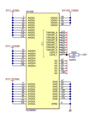
"The KSZ9897R is a seven-port managed gigabit Ethernet switch. It has five 10BASE-Te/100BASE-TX/1000BASE-T physical layer transceivers (PHYs) and associated MAC units, and two MAC ports with individually configurable RGMII/MII/RMII interfaces.
These two ports can be used for direct connection to a host Microprocessor or Micro controller, another Ethernet switch or an Ethernet PHY."
KSZ9896 is the same device but with only one MAC port configurable RGMII/MII/RMII interface.
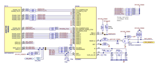
To evaluate the KSZ9897 on the board, a development board (EVB-KSZ9897) has been connected to the custom board replacing one of the Marvell Ethernet Gigabit phy 88E1510 (mac0).
Hardware changes
The KSZ9897 can be connected to the CPU SoC by three different buses: i2c, spi and mdio (in addition to the RGMII bus). But only one of them can be used at a time.
To ease the hardware change, the KSZ9897 is connected with the spi bus (spi1).
But for the final custom board the mdio bus is preferred.
The RGMII0 bus of the custom board is connected to the RGMII port 6 on the EVB-KSZ9897 (replacing the KSZ9031 device on the EVB-KSZ9897).
The spi1 bus of the custom board is connected to the SPI bus on the EVB-KSZ9897, the strap switch (sw4) on the EVB-KSZ9897 must be in "OFF" settings (to enable the spi interface).
The EVB-KSZ9897 must be powered by its own power chain.
KSZ9897 devicetree bindings
The devicetree bindings has been standardized for ksz devices but the support for the ksz9897 has been added just before the kernel 4.19 release by this commit.
It requires to add and enable the spi1 on the controller board devicetree. We can add the mcp23s08 devicetree node to check if the spi bus is working (because it's a simple/basic device).
&mcspi1 {
 status = "okay";

 /* Only cs0, cs1 and cs2 are used by spi1 */
 ti,spi-num-cs = <3>;
 gpiom1: gpio@1 {
  compatible = "microchip,mcp23s08";
  gpio-controller;
  #gpio-cells = <2>;
  microchip,spi-present-mask = <0x1>;
  reg = <1>;
  spi-max-frequency = <1000000>;
 };
};
With this we can see in dmesg:
# dmesg | grep spi
[ 3.190319] omap2_mcspi 48098000.spi: registered master spi1
[ 3.190432] spi spi1.0: setup: speed 24000000, sample trailing edge, clk inverted
[ 3.190445] spi spi1.0: setup mode 3, 8 bits/w, 44000000 Hz max --> 0
[ 3.190618] omap2_mcspi 48098000.spi: registered child spi1.0
[ 9.288140] gpiochip_find_base: found new base at 504
[ 9.288466] gpio gpiochip8: (mcp23s08.0): added GPIO chardev (254:8)
[ 9.288619] gpiochip_setup_dev: registered GPIOs 504 to 511 on device: gpiochip8 (mcp23s08.0)
Adding the KSZ9897 devicetree node (unfinished) on the spi side allows to detect the device:
ksz9897: switch@0 { compatible = "microchip,ksz9897"; reg = <0>; spi-cpha; spi-cpol; phy-mode = "rgmii-rxid"; spi-max-frequency = <44000000>; ethernet-ports { #address-cells = <1>; #size-cells = <0>; port@0 { reg = <0>; label = "lan1"; // local-mac-address = [00 00 00 00 00 00]; }; port@1 { reg = <1>; label = "lan2"; }; port@2 { reg = <2>; label = "lan3"; }; port@3 { reg = <3>; label = "lan4"; }; port@4 { reg = <4>; label = "lan5"; }; port@5 { reg = <5>; label = "cpu"; ethernet = <&cpsw_emac0>; // probably wrong should be something like "mac: ethernet@48484000" but how to select one of the two cpsw_emac ? phy-mode = "rgmii-id"; fixed-link { speed = <1000>; full-duplex; }; }; };}; |
# dmesg | grep spi
[ 3.190319] omap2_mcspi 48098000.spi: registered master spi1
[ 3.190432] spi spi1.0: setup: speed 24000000, sample trailing edge, clk inverted
[ 3.190445] spi spi1.0: setup mode 3, 8 bits/w, 44000000 Hz max --> 0
[ 3.190618] omap2_mcspi 48098000.spi: registered child spi1.0
[ 3.190645] spi spi1.1: setup: speed 1000000, sample leading edge, clk normal
[ 3.190657] spi spi1.1: setup mode 0, 8 bits/w, 1000000 Hz max --> 0
[ 3.190821] omap2_mcspi 48098000.spi: registered child spi1.1
There is something on the spi1.1 (we could use spidev driver for testing) but it's not used by any other driver (We are expecting the ksz9477_spi.ko driver).
As you can notice, the link between the ksz9897 port5 and the cpsw mac0 can't be easily described.
On other examples, there is no ambiguity because there is only one mac.
Indeed the TI CPSW is itself an Ethernet Switch.
Lets see if we can change the cpsw devicetree for the custom board.
TI CPSW (TI SoC Ethernet Switch Controller)
The TI Sitara AM57xx uses an IP from TI to provide two Gigabit Ethernet interface. This IP uses an upstream kernel driver with a standardized devicetree bindings.
The extract below shows the CPSW devicetree node with two "slave", one slave for each emac.
mac: ethernet@48484000 { compatible = "ti,dra7-cpsw","ti,cpsw"; ... davinci_mdio: mdio@48485000 { compatible = "ti,cpsw-mdio","ti,davinci_mdio"; ... }; cpsw_emac0: slave@48480200 { ... }; cpsw_emac1: slave@48480300 { ... }; ...}; |
The mac node, cpsw_emac0 and the cpsw_emac1 nodes are completed and enabled from the devicetree specific to the controller board:
&mac { status = "okay"; dual_emac;};&cpsw_emac0 { phy_id = <&davinci_mdio>, <0>; phy-mode = "rgmii"; dual_emac_res_vlan = <1>;};&cpsw_emac1 { phy_id = <&davinci_mdio>, <1>; phy-mode = "rgmii"; dual_emac_res_vlan = <2>;}; |
The problem with the actual devicetree binding is that the ksz9897 binding expect to use directly the node of the ethernet controller "mac: ethernet@48484000".
But the handling of the slaves is not specified from the ksz9897 binding.
Also the TI CPSW expect using the MDIO bus to connect with the PHY, not the spi bus.
After some research on the TI forum, it seems that what we want to achieve is not supported by TI and the CPSW driver, for AM3352 and AM5728 at least:
https://e2e.ti.com/support/processors-group/processors/f/processors-forum/649924/am3352-ethernet-switch-with-rmii-interface
"MAC-to-MAC configuration is not supported by TI on the CPSW of Sitara devices."
"The RMII specification defines the interface as MAC-to-PHY so Sitara SoC MACs are not tested or characterized in MAC-to-MAC topologies. This applies to both SW and HW."
https://e2e.ti.com/support/processors-group/processors/f/processors-forum/711394/linux-am5728-mac-to-external-switch
"EMAC connection to an external switch is not an use case supported by TI. Sorry, we cannot offer assistance on this issue."
https://github.com/Microchip-Ethernet/UNG8071/blob/master/KSZ/kernels/linux-3.18/drivers/net/ethernet/cadence/macb.c
"The SOC MAC driver need some modification. For reference please see the macb driver (Atmel SAMA5 SOC mac driver)."
https://github.com/Microchip-Ethernet/EVB-KSZ9477/tree/master/KSZ/linux-drivers/ksz9897/linux-5.3/drivers/net/ethernet
"drivers hacked by microchip for the kernel 4.9, 4.19, 5.3 but only for some vendors: cadence, freescale, micrel"
DSA (Distributed Switch Architecture) Understanding
On the public Linux kernel mailing list for Network devices (netdev) there is a discussion about DSA switch with an AM572x cpu (cpsw ip/driver) and a KSZ9897 ethernet switch.
This is a good source of information about potential issue for such setup.
It show how to modify the devicetree, configure the network interfaces and use ethtool to analyse network statistics.
In the end, the user (after having patched/hacked its kernel) seems (unconfirmed) to be able to use the ethernet switch.
At least we should be able to do the same step on the custom board.
Hardware issues with the prototype
During test we've discovered hardware issue.
- Power supply issue. The green (power) led is blinking and the ethernet switch device is really hot. There is a high power consumption on the 3,3V power supply (1,5A).
This is due to a misleading screen printing on the Microchip evaluation board.
The 3,3V power supply was connected to 1,2V DVDDL for a long time (several hours) over the Absolute Maximum ratings.
While investigating this issue several devices was removed from the board (mainly LAN7801 and KSZ9031 along some resistors).
- TXC (RGMII) was disconnected (broken cable)
The link between the Ethernet switch and the CPU requires to add some cable to connect each MAC together. One of the cable (TXC) was broken.
Conclusion
To conclude:
- MAC-to-MAC doesn't seem officially supported by the CPSW linux driver/devicetree but there were several (successful ?) attempts.
- Hardware issue maybe damage the board.
Is the modifications we did seemed to be correct? Is there another modification we must do to allowing the use of this ethernet switch?