This thread has been locked.

If you have a related question, please click the "Ask a related question" button in the top right corner. The newly created question will be automatically linked to this question.

AM6442: OSPI0_DQS and OSPI0_LBCLKO

Guru 10095 points
Part Number: AM6442

Hi Support Team,

My customer is reviewing the schematics for a board that uses AM6442.
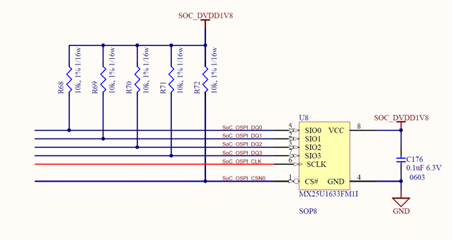
My customer is using QSPI, and just to be sure, please check the following schematic
for the pin connections of OSPI0_DQS and OSPI0_LBCLKO.


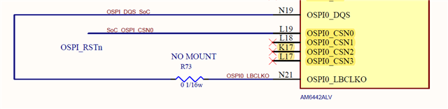
I have checked the following thread, should each pin be NC?

https://e2e.ti.com/support/processors-group/processors/f/processors-forum/1033175/am6442-connections-for-ospi-unused-pins

Best regards,
Kanae

  • Is your customer planning to boot from the QSPI device?  What clock frequency are they planning to use when communicating with the QSPI device during normal operation?

  • Hi Peaves,

    Thank you for your reply.

    My customer plans to boot from the QSPI device.

    The clock frequency that is planned to be used when communicating
    with the QSPI device during normal operation is to be used at a low speed
    below the internal clock (50MHz).

    Best regards,
    Kanae

  • It is not necessary to loop the OSPI0_LBCLKO pin to the OSPI0_DQS pin when communicating with attached device using a clock frequency that is equal to or less than 50 MHz. However, an external pull-up resistor is required for the OSPI0_LBCLKO pin of SR1.0 devices. This pull-up is needed because the OSPI0_LBCLKO input buffer is enabled by default and we cannot allow the input to float when enabled. The default setting will be changed for SR2.0 devices, such that the input buffer will be disable by default on SR2.0 devices. 

    Regards,
    Paul

  • Hi Paul,

    Thank you for your reply.
    I understand that the OSPI0_LBCLKO pin and the OSPI0_DQS pin
    should be NC (i.e. Open) when communicating with the connected device
    at a clock frequency of 50MHz or lower.

    I will also share with my customer that for SR1.0 devices,
    there must be an external pull-up resistor on the OSPI0_LBCLKO pin.

    Best regards,
    Kanae